Connectable cable organizer

a technology of connectors and organizers, which is applied in the direction of electrical devices, pipe supports, mechanical devices, etc., can solve the problems of complex manufacturing process, high manufacturing cost and process several drawbacks of existing cable clips, etc., and achieves the effect of simple structure and easy manufacturing

Active Publication Date: 2018-01-30
MAXDAO
View PDF39 Cites 20 Cited by
  • Summary
  • Abstract
  • Description
  • Claims
  • Application Information

AI Technical Summary

Benefits of technology

[0007]In order to solve the above issues, the present invention provides a connectable cable organizer that is convenient for holding the cable in position and for removing the cable from the cable organizer. The cable organizer of the present invention has a simple structure that can be easily manufactured and can securely hold the cable without damaging the cable.
[0014]The structure and design of the present invention is simple, easy to manufacture with low production cost, and convenient for installation and disassembly. Due to the integrated structural configuration, there is no cutting point on the positioning unit. Therefore, the cable can be slid or rotate for cable positioning adjustment after the cable is held by the positioning unit so as to prevent any damage of the cable. The overall structure is compact that multiple connectable cable organizers can be interconnected with each other, so as to ensure the reliability of the connection. The organizing body, the organizing adapter, the positioning unit, and the locking unit are integrated to form a single configuration so as to ensure the stability of the connection and securing of the cable. Since the reinforcing rim is formed around the peripheral edge of the through hole to engage with the reinforcing ribs, the connection between two connectable cable organizers can be stabilized and ensured. The match between the locking head and the organizing adapter will enhance the firmness of the connection between two connectable cable organizers.
[0015]The first positioning walls are perpendicularly extended from the bottom side of the organizing body and the second positioning walls are integrally, inclinedly and inwardly extended from the top edges of the first positioning walls. A space is formed between two inner edges of said supporting walls. The third positioning walls are integrally extended from the top edges of the second positioning walls, wherein the two third positioning walls are upwardly and perpendicularly extended with respect to the bottom side of the organizing body. The retention grooves are inwardly formed at the top edges of the third positioning walls, wherein the cable retention space is formed below the retention grooves, above the supporting walls, and between the third positioning walls for matching with the diameter size of the cable. As a result, the entire device meets the required design and standard, which is simple and stable. The reinforcing ribs are outwardly extended from two side edges of each of the locking heads to stabilize and ensure the connection between two connectable cable organizers. Since the guiding walls bent outwardly from the top edge of the positioning panels, the guiding walls the cable organizer will bias against the bottom side of the organizing body of another cable organizer, so as to prevent any wobbling movement between the two cable organizers and to enhance the stabilization between the two cable organizers.

Problems solved by technology

However, the existing cable clip has several drawbacks.
The existing cable clip generally has a complicated structure to fasten with the cable, such that the fastening operation and the unfastening operation of the existing cable clip are relatively complicated.
Thus, the manufacturing cost and process of the existing cable clip is relatively high and complicated due to its structure, such that the existing cable clip cannot be mass produced.
In addition, the major problem of the existing cable clip is that since the cable must be securely retained by the existing cable clip, the cable cannot be rotated with respect to the existing cable clip.
In other words, when the cable is forced to rotate, the outer surface of the cable, i.e. the insulating barrier, will be damaged by the existing cable clip.
As a result, the conductor wires will be exposed and will not be protected by the insulating barrier at all.

Method used


Image

  • Connectable cable organizer
  • Connectable cable organizer
  • Connectable cable organizer

Examples


Embodiment Construction

[0022]The following description is disclosed to enable any person skilled in the art to make and use the present invention. Preferred embodiments are provided in the following description only as examples and modifications will be apparent to those skilled in the art. The general principles defined in the following description would be applied to other embodiments, alternatives, modifications, equivalents, and applications without departing from the spirit and scope of the present invention.

[0023]The following further describes the present invention in detail with appended figures.

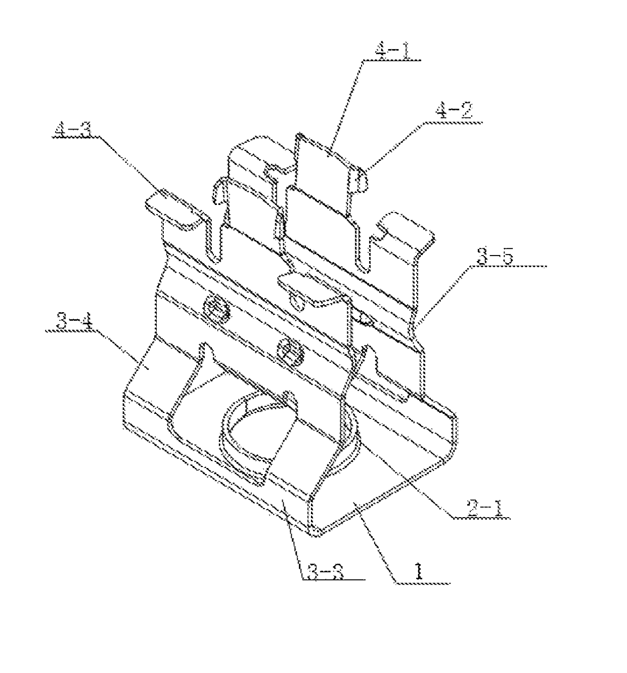
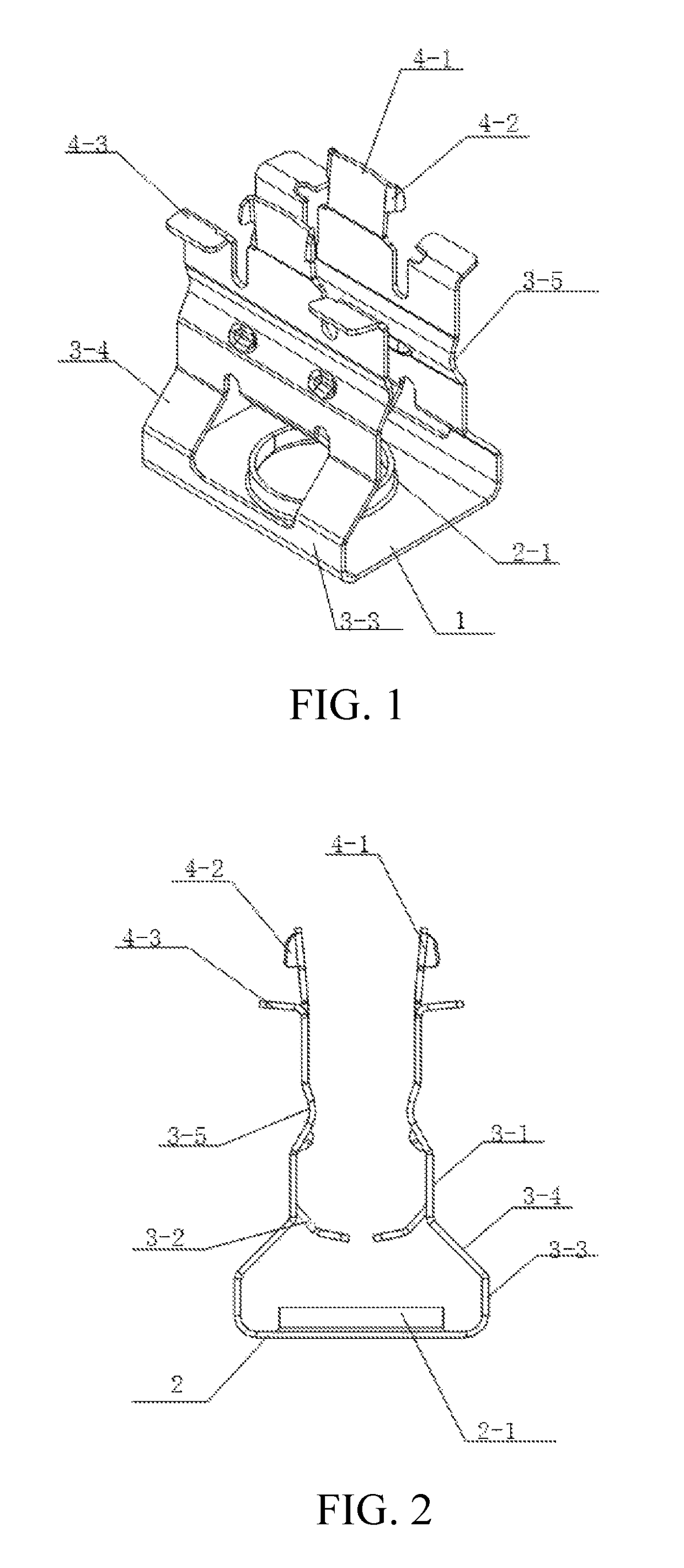
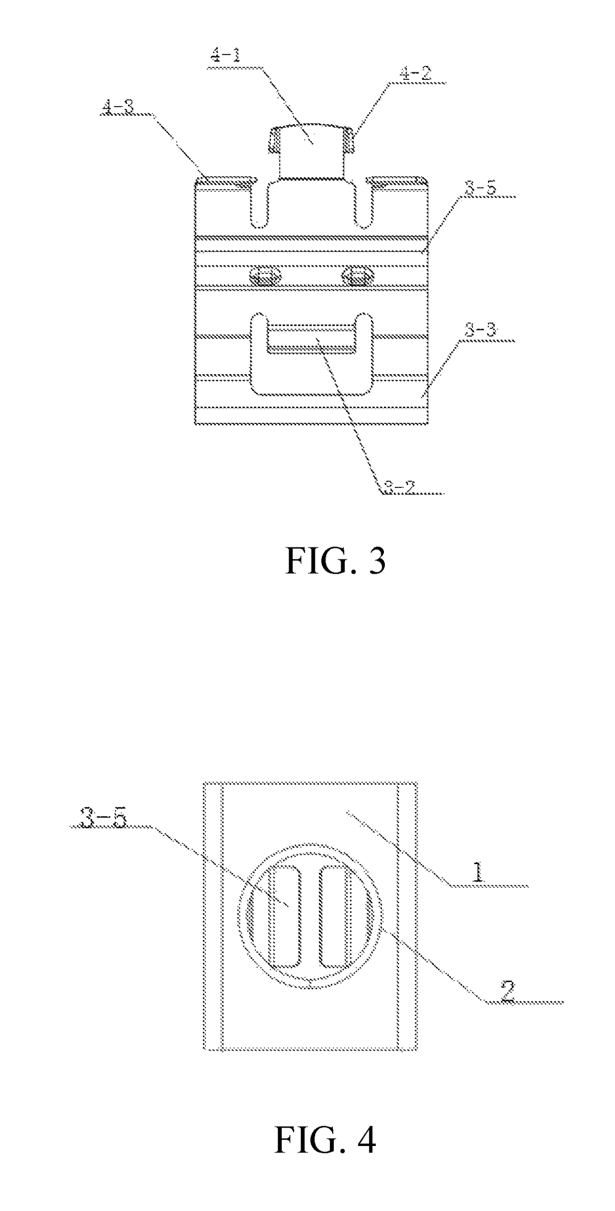
[0024]Referring to FIGS. 1 to 4 of the drawings, a cable organizer comprises an organizing body 1 generally having a U-shaped cross section, an organizing adapter 2 provided at a bottom side of the organizing body 1, a positioning unit upwardly extended from two sides of the bottom side of the organizing body 1, and a locking unit. The organizing adapter 2 has a through hole formed at the bottom side of th...


PUM


Abstract

A connectable cable organizer includes an organizing body, an organizing adapter having a through hole formed at the bottom side of the organizing body, two positioning panels upwardly and inclinedly extended from two sides of the bottom side of the organizing body for receiving a cable between the positioning panels, and two locking heads integrally and upwardly extended from top edges of the positioning panels. The cable is disposed at a cable retention space between the positioning panels, such that the cable is clamped between the positioning panels while the cable is slidable and rotatable at the cable retention space. Two connectable cable organizers are detachably coupled with each other by inserting the locking unit of one connectable cable organizer into the through hole of another connectable cable organizer to hold the cables side-by-side.

Description

CROSS REFERENCE OF RELATED APPLICATION[0001]This is a non-provisional application that claims priority to Chinese application number 2016200335866, filing date Jan. 14, 2016, the entire contents of each of which are expressly incorporated herein by reference.NOTICE OF COPYRIGHT[0002]A portion of the disclosure of this patent document contains material which is subject to copyright protection. The copyright owner has no objection to any reproduction by anyone of the patent disclosure, as it appears in the United States Patent and Trademark Office patent files or records, but otherwise reserves all copyright rights whatsoever.BACKGROUND OF THE PRESENT INVENTION[0003]Field of Invention[0004]The present invention relates to a cable clipping apparatus, and more particular to a connectable cable organizer that can quickly retain the cable and to allow the cable to be rotated freely.[0005]Description of Related Arts[0006]Cables, such as electric cables and signal cables, are commonly const...

Claims


Application Information

Patent Timeline
Patent Type & Authority Patents(United States)
IPC IPC(8): F16L3/22F16L3/12
CPCF16L3/222F16L3/1222F16L3/1218F16L3/16H02G3/32
Inventor LENG, JUN HUA
Owner MAXDAO
Why Eureka
Try Eureka