
Multiple-axis magnetic bearing and control of the magnetic bearing with active switch topologies

a magnetic bearing and switch topology technology, applied in the field of multi-axis active magnetic bearings, can solve the problems of reducing the service life of the bearing, requiring more lubrication, and not being suitable for compressor speeds above 30,000 revolutions per minute,

Active Publication Date: 2018-02-13
CARRIER CORP
View PDF55 Cites 0 Cited by
  • Summary
  • Abstract
  • Description
  • Claims
  • Application Information

AI Technical Summary

Benefits of technology

The patent text discusses the use of traditional centrifugal compressors in the HVAC industry and the issues related to power consumption, oil consumption, and lubrication systems. The text introduces ceramic roller bearings as an alternative to traditional bearings, but they are not suitable for high speeds. Gears are then introduced as a solution, but they require more lubrication, create noise and vibration, and consume more power. The technical effect of this patent text is to provide a solution for the high-speed requirements of centrifugal compressors in the HVAC industry without using traditional bearings or excessive lubrication, noise, and vibration.

Problems solved by technology

Ceramic roller bearings are not suitable for compressor speeds above 30,000 revolutions per minute (rpm), as these bearings generate excessive heat at high rpms.
While gears are a proven technology, they require more lubrication, create excessive noise and vibration, and consume more power.
However, the high costs of these AMBs including their controls have limited the wide scale implementation of magnetic bearings, particularly within the HVAC industry.
The additional power amplifiers make implementing the AMB topology more expensive and complex.

Method used


Image

  • Multiple-axis magnetic bearing and control of the magnetic bearing with active switch topologies
  • Multiple-axis magnetic bearing and control of the magnetic bearing with active switch topologies
  • Multiple-axis magnetic bearing and control of the magnetic bearing with active switch topologies

Examples


Embodiment Construction

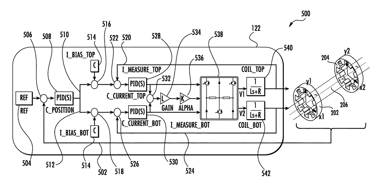
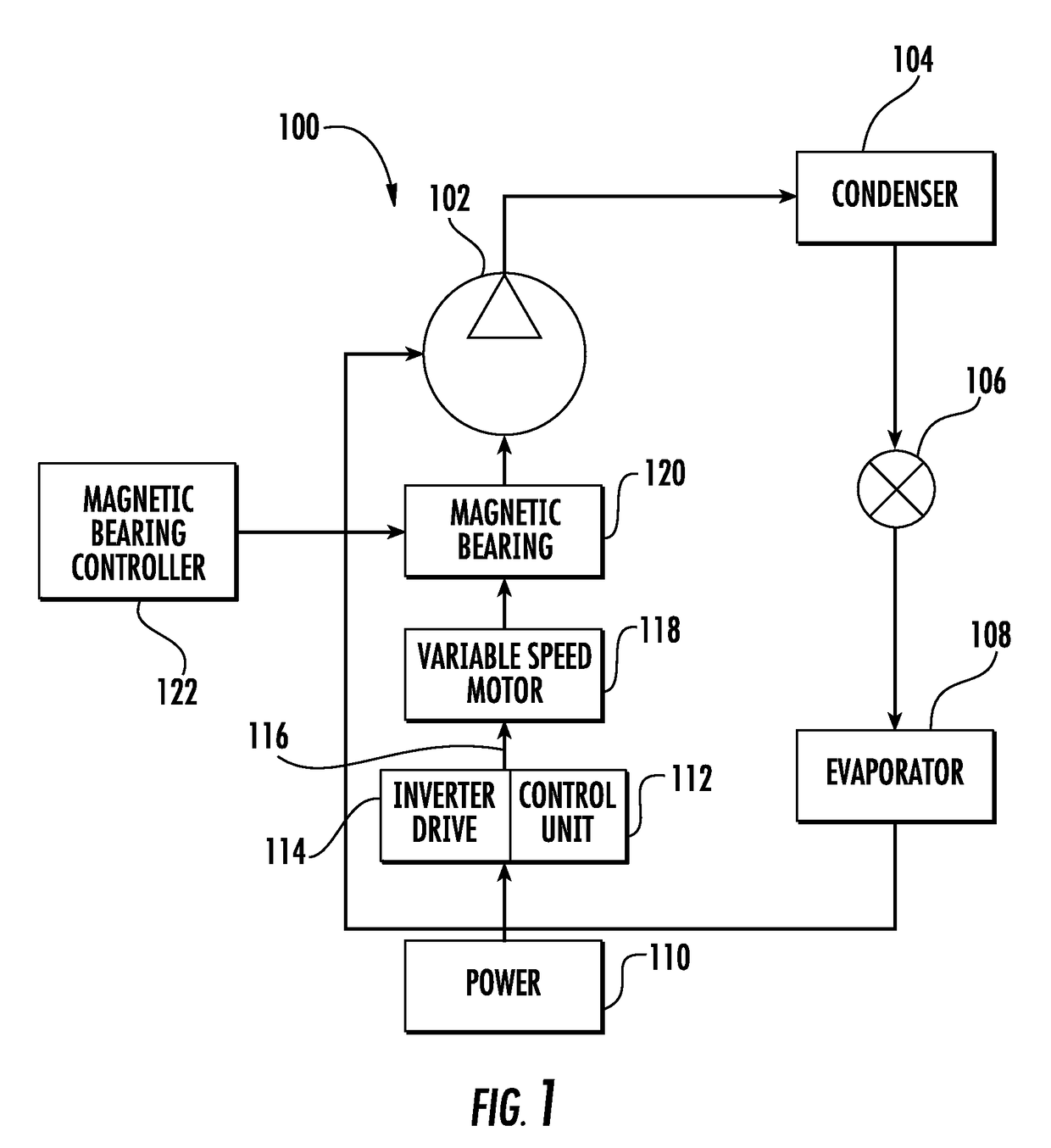
[0016]Embodiments include a vapor compression-type HVAC system that includes a multiple-axis AMB for supporting a rotor shaft. The rotor shaft connects a compressor to a motor and is constrained by the AMB, which receives one or more energizing signals to adjust the radial position of the rotor shaft. In an exemplary embodiment, the AMB may include a reduced switch multi-phase circuit topology with unidirectional active current switches. This exemplary embodiment with the multi-phase circuit topology reduces the number of diodes and switches that are used to constrain the radial position of the rotor shaft. The HVAC system also includes a controller having a processor for implementing a control algorithm for controlling the bias current used to control the coils in the AMB in order to adjust the position of the rotor shaft.

[0017]Referring now to the drawings, FIG. 1 illustrates an exemplary refrigerant vapor compression system 100 including a variable speed motor 118 having a rotor ...


PUM


Abstract

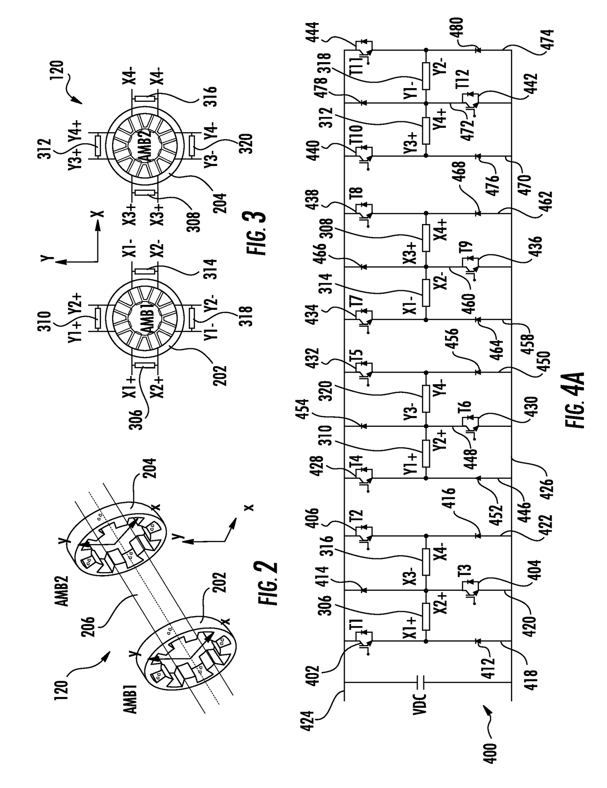
A magnetic bearing system (120) includes a first active magnetic bearing (AMB) (202) including a first group of electromagnetic actuators (306, 310, 314, 318) to support a shaft and a second AMB (204) including a second group of electromagnetic actuators (308, 312, 316, 320) to support the shaft. A controller for the two AMB's includes a multi-phase topology (400) with a plurality of active current switches for controlling the electromagnetic actuators (306-320) of each of the first AMB (202) and the second AMB (204). Each electromagnetic actuator (306, 310, 314, 318) of the first AMB (202) is electrically coupled to an electromagnetic actuator (308, 312, 316, 320) of the second AMB (204). Each pair of coupled electromagnetic actuators (306, 316) is respectively connected to three phase legs (418, 420, 422) of the topology (400) of the controller, whereby one end (X2+, X3−) of each of the electromagnetic actuators of a pair (306, 316) is connected to one phase leg (420) of the topology (400) and the other ends (X1+, X4−) are respectively connected to two further phase legs (418, 422) of the topology (400). The controller is operable to receive information indicative of a position of the rotor shaft and supply an adjustment signal to the magnetic bearing system (120) to adjust the position of the shaft.

Description

FIELD OF INVENTION[0001]Embodiments relate generally to refrigerant vapor compression systems for residential or light commercial heating and refrigeration applications and, more particularly, to one or more multiple-axis active magnetic bearings (AMB) and control of the AMBs that are connected to a rotor shaft of the refrigerant vapor compression system.DESCRIPTION OF RELATED ART[0002]Traditional centrifugal compressors in the heating ventilation and air conditioning (HVAC) industry use roller bearings and hydrodynamic bearings, both of which consume power, require oil, and a lubrication system. Ceramic roller bearings, which avoid issues related to oil and power consumption, have been introduced in these HVAC applications. Ceramic roller bearings are not suitable for compressor speeds above 30,000 revolutions per minute (rpm), as these bearings generate excessive heat at high rpms. Gears operate at high rpms and are typically used in lieu of ceramic roller bearings. While gears ar...

Claims


Application Information

Patent Timeline
Patent Type & Authority Patents(United States)
IPC IPC(8): F04D29/058F16C32/04F25B31/02F25B1/00
CPCF16C32/0489F04D29/058F16C32/0444F16C32/0457F25B1/005F25B31/026F16C32/0487F16C2362/52F16C32/0451
Inventor KSHIRSAGAR, PARAGYAN, PENG
Owner CARRIER CORP
Learn More