Soft transition on all switching elements two transistors forward converter

a technology of forward converter and switching element, which is applied in the direction of electric variable regulation, process and machine control, instruments, etc., can solve the problems of causing noise in the system, and affecting the efficiency of the converter, so as to eliminate the loss of reverse recovery, eliminate the loss, and the effect of low leakage inductan

Active Publication Date: 2018-02-20
ROMPOWER TECH HLDG LLC
View PDF17 Cites 18 Cited by
  • Summary
  • Abstract
  • Description
  • Claims
  • Application Information

AI Technical Summary

Benefits of technology

[0008]According to this invention we are able to eliminate the disadvantages presented in analyzing the prior art. By controlling the timing of the drive signal for SR1 and SR2 we are able to create zero voltage switching conditions for M1 and M2 eliminating the losses associated with the discharge of the parasitic capacitances of M1, M2 and the transformer. In the same time we are able to eliminate not only the cross conduction between M1, M2 and the SR2 but we are able to eliminate also the reverse recovery losses associated with the body diode of SR2. The method used in this invention offers soft transition on the primary switchers and also secondary switchers in application with very low leakage inductance. In most of the application to obtain soft switching on the primary switchers, the transformer has to have a larger leakage inductance and in some cases, additional inductive elements are placed in the primary or the secondary of the transformer.
[0009]In one of its features, the method of the invention can improve any forward topology operation to achieve efficient resonant transitions by actively shorting the magnetizing inductance and release the short at another time thus producing lower switching losses independent of frequency. In another aspect of the invention, the current from the output inductor is allowed to go negative before the freewheeling synchronous rectifier is turned off, pushing the current back into the primary to create a soft transition across the switching elements before they are turned on. In another aspect of the invention, a current source is used to inject a negative current through the freewheeling synchronous rectifier before is turned off with the purpose of transferring the current into the primary to discharge the parasitic capacitances of the primary switchers before they are turned on.
[0012]In another embodiment, the present invention also provides a resonant transition control method for a forward converter (e.g a two transistor forward converter) that has two power trains each of which has a freewheeling rectifier. The method of the invention comprises interleaving the two power trains so that each power train in forward mode provides current to the other power train, so that its freewheeling synchronous rectifier has negative current, to create a negative current through the freewheeling synchronous rectifiers of the converter to minimize the turn on losses.

Problems solved by technology

In addition to this, there are large current spikes by the forceful discharge of the parasitic capacitance, which created noise in the system.
The cross conduction it is a very dissipative phenomenon which negatively affects the efficiency of the converter.
Function of the reverse recovery characteristics of the body diode of SR2 the losses can be significant, though possible lower then cross conduction losses.

Method used


Image

  • Soft transition on all switching elements two transistors forward converter
  • Soft transition on all switching elements two transistors forward converter
  • Soft transition on all switching elements two transistors forward converter

Examples


Embodiment Construction

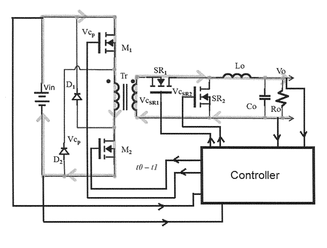
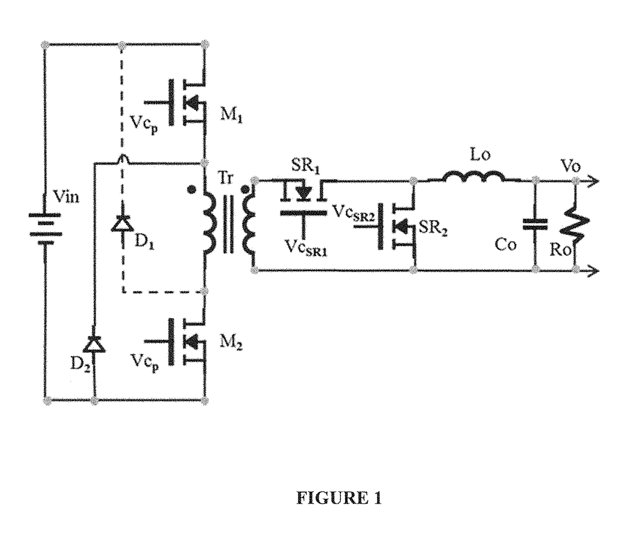
[0026]As described above, the present invention provides a method for providing a forward converter (e.g. a two transistors forward converter) with lower switching losses. Its principles are described herein in connection with a two transistors forward converter, and from that description the manner in which the present invention can be applied to various forward converters will be apparent to those in the art.

[0027]The mode of operation in this invention to an embodiment of a two transistors forward converter is described in FIG. 4, FIG. 5, FIG. 6, FIG. 7, FIG. 8, FIG. 9, FIG. 10 and FIG. 11. In FIG. 5 are depicted the key waveforms, Vcp the drive signal for M1 and M2, the current through M1 and M2, Vcsr1 and Vcsr2 which are the control voltages for SR1 and Sr2, The voltage across the primary switchers in FIG. 5e, The magnetizing current in FIG. 5f, the current through the SR1 and the current through SR2.

[0028]We have identified four modes of operation of this embodiment.

[0029]To-T...


PUM


Abstract

A method is shown to improve any forward topology operation to achieve efficient resonant transitions by actively shorting the magnetizing inductance and release the short at another time thus producing lower switching losses independent of frequency. In another embodiment of this invention the current from the output inductor is allowed to go negative before the freewheeling synchronous rectifier is turned off, pushing the current back into the primary to create a soft transition across the switching elements before they are turned on. In another embodiment of the invention a current source is used to inject a negative current through the freewheeling synchronous rectifier before is turned off with the purpose of transferring the current into the primary to discharge the parasitic capacitances of the primary switchers before are turned on. An optimized control method can be utilized to tailor the frequency to create the necessary conditions requested by the embodiments of the invention.

Description

RELATED APPLICATION / CLAIM OF PRIORITY[0001]This application is related to and claims priority from U.S. provisional application Ser. No. 61 / 821,902, filed May 10, 2013, which provisional application is incorporated by reference herein.INTRODUCTION[0002]The Two Transistor Forward topology is the most popular topology for off line applications. Applications include AC to DC adapters for desktop computers, servers, and many other power applications in medium power levels. The Two Transistor Forward topology is presented in FIG. 1. Two primary switching elements, M1 and M2 and two reset rectifiers D1 and D2 compose it. In the secondary there are two rectifier elements SR1 and SR2. During the conduction of the primary switchers, M1 and M2, the power is transferred to the secondary via SR1 and Lo. During that period of time, there is a forward energy transfer to the secondary. The input voltage Vin is applied across the primary winding. If the polarity of the transformer is as presented i...

Claims


Application Information

Patent Timeline
Patent Type & Authority Patents(United States)
IPC IPC(8): H02M3/335H02M1/00
CPCH02M3/33592H02M3/3353H02M3/33553Y02B70/1491Y02B70/1433Y02B70/1475H02M2001/0058H02M1/12Y02B70/10H02M1/0058
Inventor JITARU, IONELDAVILA, MARCO ANTONIO
Owner ROMPOWER TECH HLDG LLC
Why Eureka
Try Eureka