Pinion bearing unit

Active Publication Date: 2018-02-27
AB SKF
View PDF14 Cites 3 Cited by
  • Summary
  • Abstract
  • Description
  • Claims
  • Application Information

AI Technical Summary

Problems solved by technology

The stiffness of such a bearing combination is not optimal in view of the dif

Method used


Image

  • Pinion bearing unit
  • Pinion bearing unit

Examples


Embodiment Construction

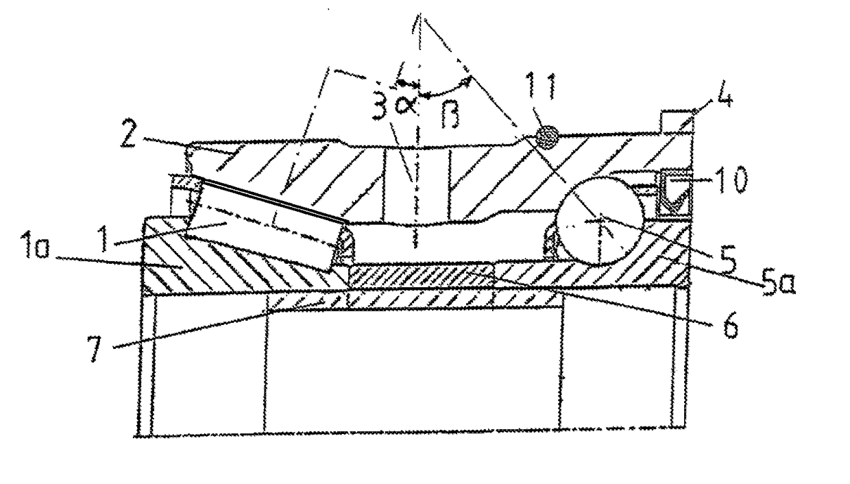
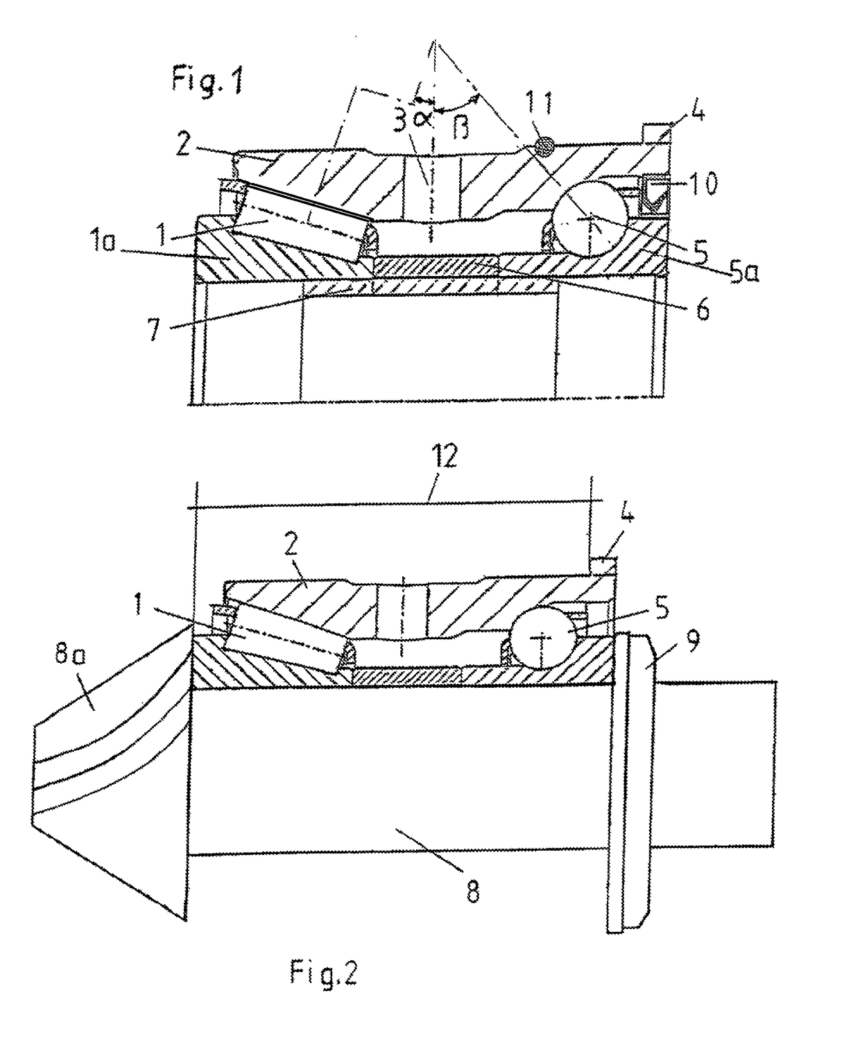
[0010]FIG. 1 shows in cross-section the upper half of a pinion bearing unit according to the invention, wherein a two-row bearing unit consists on the pinion head side of a friction optimized taper roller bearing 1 and on the pinion tail side of an angular ball bearing 5. Both rows of bearings have a common one-piece outer race ring 2, in which are provided two opposite oil bores 3 (only one being shown), whereas the inner race rings 1a and 5a, resp. are axially spaced apart by a spacing sleeve 6. At the side of the common outer race ring 1 remote from the pinion head there is provided an external flange 4 for mounting purpose. The bearings 1, 5 are mounted as preloaded bearings in back-to-back relation with an optimized preload with reference to stiffness and friction losses.

[0011]In order to obtain such a high bearing stiffness as possible and at the same time a lower bearing friction and reduced effect loss also at extended bearing life span, it is necessary to design the interna...


PUM


Abstract

A bearing unit, for supporting a pinion shaft having at one side a pinion head, includes a taper roller bearing and an angular ball bearing, the bearings having a common outer race ring and separate inner race rings. The inner race rings are spaced apart a distance along the pinion shaft, and the taper roller bearing has a contact angle α from 15° to 20° for absorbing mainly the radial force component of the tooth force at the pinion head, and the one-row angular ball bearing has a contact angle β of between 35° and 45° for absorbing mainly the axial force coming from the gear mesh and that induced by the taper roller bearing.

Description

BACKGROUND OF THE INVENTION[0001]The present invention refers to a hybrid pinion bearing unit for use in a motor vehicle front axle differential with negative hypoid offset and also for motor vehicle power transfer units, and the purpose is to provide an application-oriented optimization of the bearing assembly of the pinion shafts in drivelines. In relation to the present drivelines, due to the more and more increasing negative hypoid offset (i.e. the rotational axis of the differential is situated below the corresponding pinion shaft) in the future, in front axle differentials and the conversion of the helical directions associated therewith of the taper drive, the force conditions in the hypoid gearing will also change. Thereby the pinion axle in tractive operation in the future will be pulled into the crown wheel gears. In order to still be able to obtain such a low clearance of the flank of a tooth as possible, it is above all necessary to have a bearing assembly which is optim...

Claims


Application Information

Patent Timeline
IPC IPC(8): F16C19/49F16C41/04F16H57/021F16C33/30F16C33/60
CPCF16C19/497F16C33/303F16C33/60F16H57/021F16C41/04F16C2361/61F16C2240/30
Inventor WOLF, THOMAS
Owner AB SKF
Why Eureka
Try Eureka