Torsional vibration damper

a torsional vibration and damper technology, applied in the direction of vibration suppression adjustment, mechanical equipment, gearing, etc., can solve the problem that the vibration damping device may not be easily fitted into the powertrain, and achieve the effect of suppressing torsional vibration, enhancing the vibration damping performance of the torsional vibration damper, and increasing the mass of the rotary element serving as an inertial mass

Active Publication Date: 2018-02-27
TOYOTA JIDOSHA KK
View PDF22 Cites 1 Cited by
  • Summary
  • Abstract
  • Description
  • Claims
  • Application Information

AI Technical Summary

Benefits of technology

[0008]Aspects of the present invention have been conceived noting the foregoing technical problems, and it is therefore an object of the present invention is to provide a torsional vibration damper in which a vibration damping performance in a low speed range is enhanced without being elongated in an axial direction.
[0011]In the torsional vibration damper according to the present application, the input element and the output element connected through the elastic member are rotated relatively by pulsation of torque applied to the input element. Consequently, the remaining rotary element is rotated by a differential action of the planetary unit to establish an inertial force counteracting the torque pulse in accordance with a mass thereof. That is, the rotary element other than the input element and the output element serves as an inertial mass to suppress torsional vibrations. According to the present application, a mass of the rotary member serving as an inertial mass is increased by the mass increasing portion so that vibration damping performance of the torsional vibration damper can be enhanced especially in a low speed range. In addition, the mass increasing portion is formed on the rotary member other than the input element and the output element within the vacant area where the planetary gears do not rolls thereon even if the sun element and the ring element are rotated relatively by pulsation of the torque applied to the input element. According to the present application, therefore, a mass of the rotary element serving as an inertial mass can be increased without elongating an axial length of the planetary unit.

Problems solved by technology

Consequently, the vibration damping device may not be fitted into a powertrain easily.

Method used


Image

  • Torsional vibration damper
  • Torsional vibration damper
  • Torsional vibration damper

Examples


Embodiment Construction

)

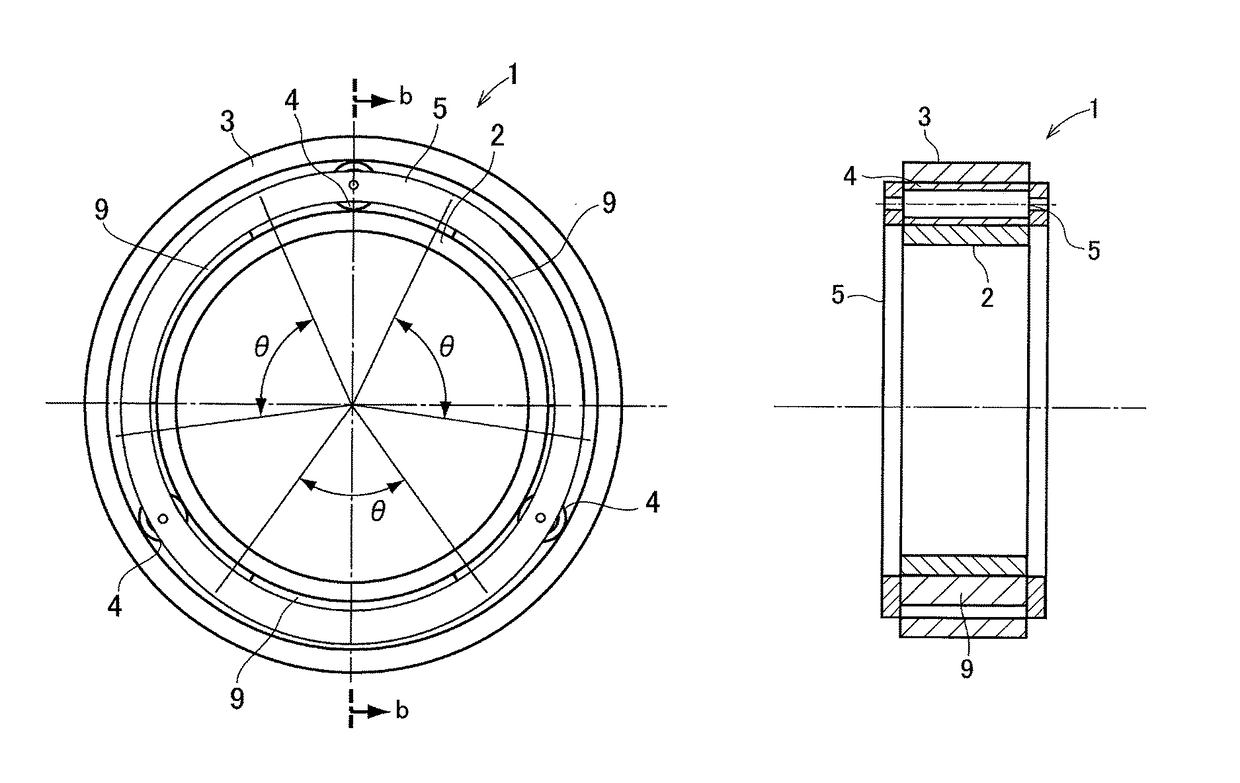
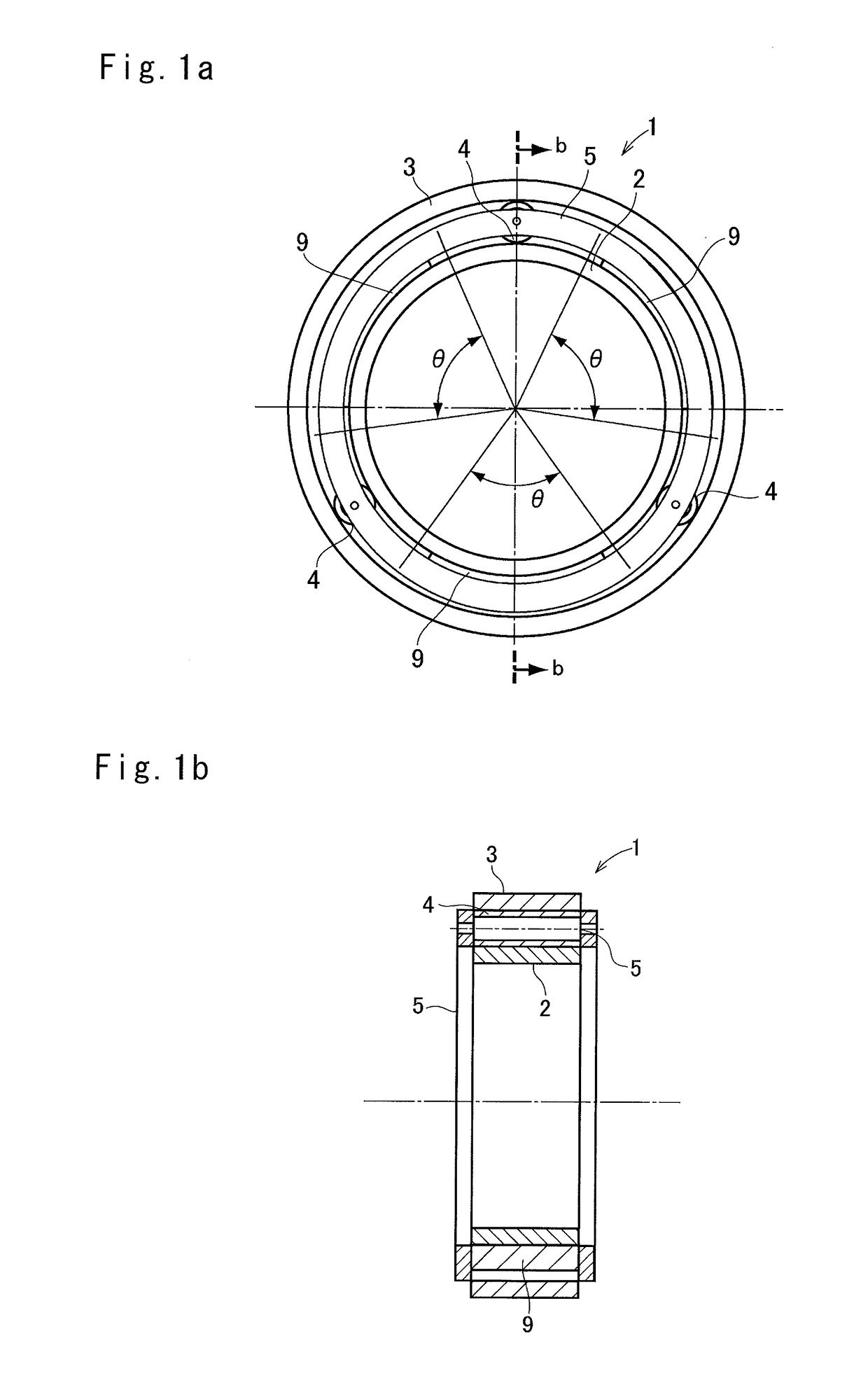
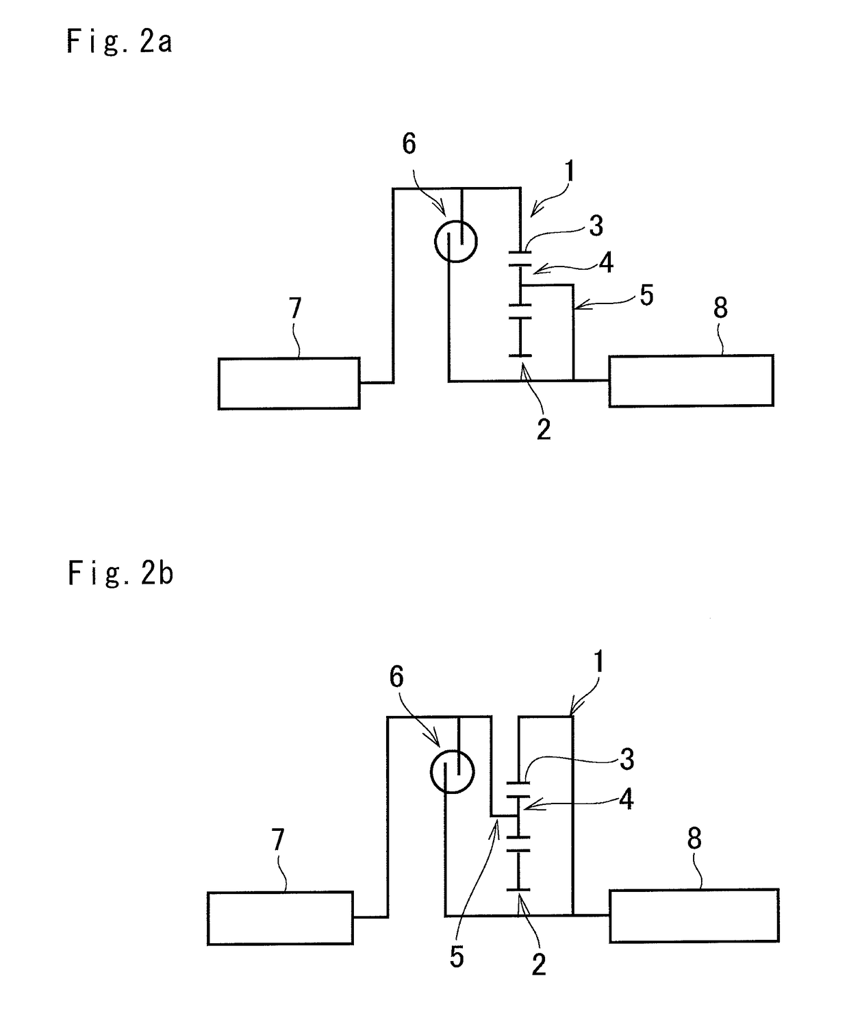
[0030]The preferred embodiments of the present application will now be explained in more detail with reference to the accompanying drawings. Referring now to FIG. 1, there is shown one example of the planetary unit 1 as a main part of the torsional vibration damper that is adapted to perform a differential action among three rotary elements. For example, a planetary gear unit and a planetary roller unit may be used as the planetary unit 1. Specifically, the planetary unit comprises a sun element 2 as a rotational center element, a ring element 3 arranged concentrically with the sun element 2, a plurality of planetary elements 4 interposed between the sun element 2 and the ring element 3, and a carrier element 5 supporting the planetary element 4 in a rotatable and revolvable manner. Given that the planetary gear unit is used as the planetary unit 1, the sun element 2 is a sun gear as an external gear, the ring element 3 is a ring gear as an internal gear, the planetary elements 4 a...


PUM


Abstract

A torsional vibration damper having enhanced vibration damping performance is provided. The torsional vibration damper comprises: a vacant area existing between an outer circumference of the sun gear and an inner circumference of the ring gear outside of a revolving range of the planetary gears revolved as a result of relative rotation between the sun and the ring gear; and a mass increasing portion that is formed on the rotary member other than an input element and an output element within the vacant area in such a manner as to protrude from the rotary member.

Description

CROSS-REFERENCE TO RELATED APPLICATIONS[0001]The present invention claims the benefit of Japanese Patent Application No. 2015-068124 filed on Mar. 30, 2015 with the Japanese Patent Office, the disclosures of which are incorporated herein by reference in its entirety.BACKGROUND[0002]Field of the Invention[0003]The present invention relates to the art of a vibration damper for suppressing torque pulses (i.e., vibrations) by an inertial torque.[0004]Discussion of the Related Art[0005]U.S. Pat. No. 5,863,274 describes a torsional vibration damping apparatus comprising a planetary transmission in which a sun gear serves as an input element, and a carrier or a ring gear serves as an output element. In the planetary transmission, the sun gear is connected to a first mass, and the carrier or the ring gear is connected to a second mass. According to the teachings of U.S. Pat. No. 5,863,274, coil springs are interposed between any of two rotary elements of the planetary transmission in such a...

Claims


Application Information

Patent Timeline
Patent Type & Authority Patents(United States)
IPC IPC(8): F16H15/14F16H1/28F16F15/14
CPCF16H1/28F16F15/145F16F15/12F16F15/30F16F15/13157F16F15/1478
Inventor TAKAHASHI, YUYASEKIGUCHI, TADASHIMATSUMOTO, MORIHIRO
Owner TOYOTA JIDOSHA KK
Why Eureka
Try Eureka