Supercharge Your Innovation With Domain-Expert AI Agents!

Systems for two-stage biomass pyrolysis

a biomass pyrolysis and biomass technology, applied in biofuels, products, chemistry apparatuses and processes, etc., can solve the problems of lowering efficiency and yield below commercially-viable levels, neither of these options is conducive to the design of a large, commercial-scale pyrolysis system, and lack of residence time. achieve the effect of facilitating transportation

Active Publication Date: 2018-03-06
PHILLIPS 66 CO
View PDF1 Cites 0 Cited by
  • Summary
  • Abstract
  • Description
  • Claims
  • Application Information

AI Technical Summary

Benefits of technology

The patent describes a reactor system that can hold and recycle carbon-based materials. The system has two stages: a first stage where solid materials are heated and vaporized, and a second stage where the vaporized materials are further heated and cooled. The second stage has a special area that allows the vapors to escape while the solid materials are retained. This area also allows the vapors to move upward through the solid materials and out of the reactor. The system also has a solids outlet for removing the solid materials. The technical effects of this system are improved carbon recycling and reduced energy consumption.

Problems solved by technology

A major barrier to commercial implementation of this pyrolysis technology for production of biofuels is that the condensable pyrolysis vapors include many highly-reactive intermediate compounds comprising radicals.
These compounds rapidly react to form secondary compounds that are difficult to upgrade to transportation fuels.
However, neither of these options is conducive to the design of a large, commercial-scale pyrolysis system.
Unfortunately, small volume reactors often lack sufficient residence time to completely pyrolyze the feedstock, thereby lowering efficiency and yield beneath commercially-viable levels.
Alternatively, increasing the throughput of sweep gas (or sweep gas rate) also decreases efficiency by: 1) excessively diluting the pyrolysis vapors, making subsequent catalytic upgrading less efficient, 2) requiring more energy to heat the larger volume of sweep gas, and 3) potentially increasing char entrainment in the pyrolysis vapors leaving the reactor.
Unfortunately, auger-type reactors become progressively less efficient as their size is increased to a commercial-scale throughput.
For example, increasing the diameter or cross-section of an auger-type reactor leads to progressively less efficient mixing, and thus, less efficient heating of the feedstock.
This decreases pyrolysis vapor yield.
Alternatively, increasing the reactor length to achieve increased biomass residence time (thereby increasing pyrolysis vapor yield) simultaneously decreases efficiency by increasing the volume of heated sweep gas required to minimize pyrolysis vapor residence time (leading to the problems discussed above).
The disadvantages of not providing sufficient biomass residence time include decreased yield (via incomplete pyrolysis) and the potential for clogging of the pyrolysis system due to continued pyrolysis of the biomass following its removal from the reactor.

Method used


Image

  • Systems for two-stage biomass pyrolysis
  • Systems for two-stage biomass pyrolysis
  • Systems for two-stage biomass pyrolysis

Examples


Embodiment Construction

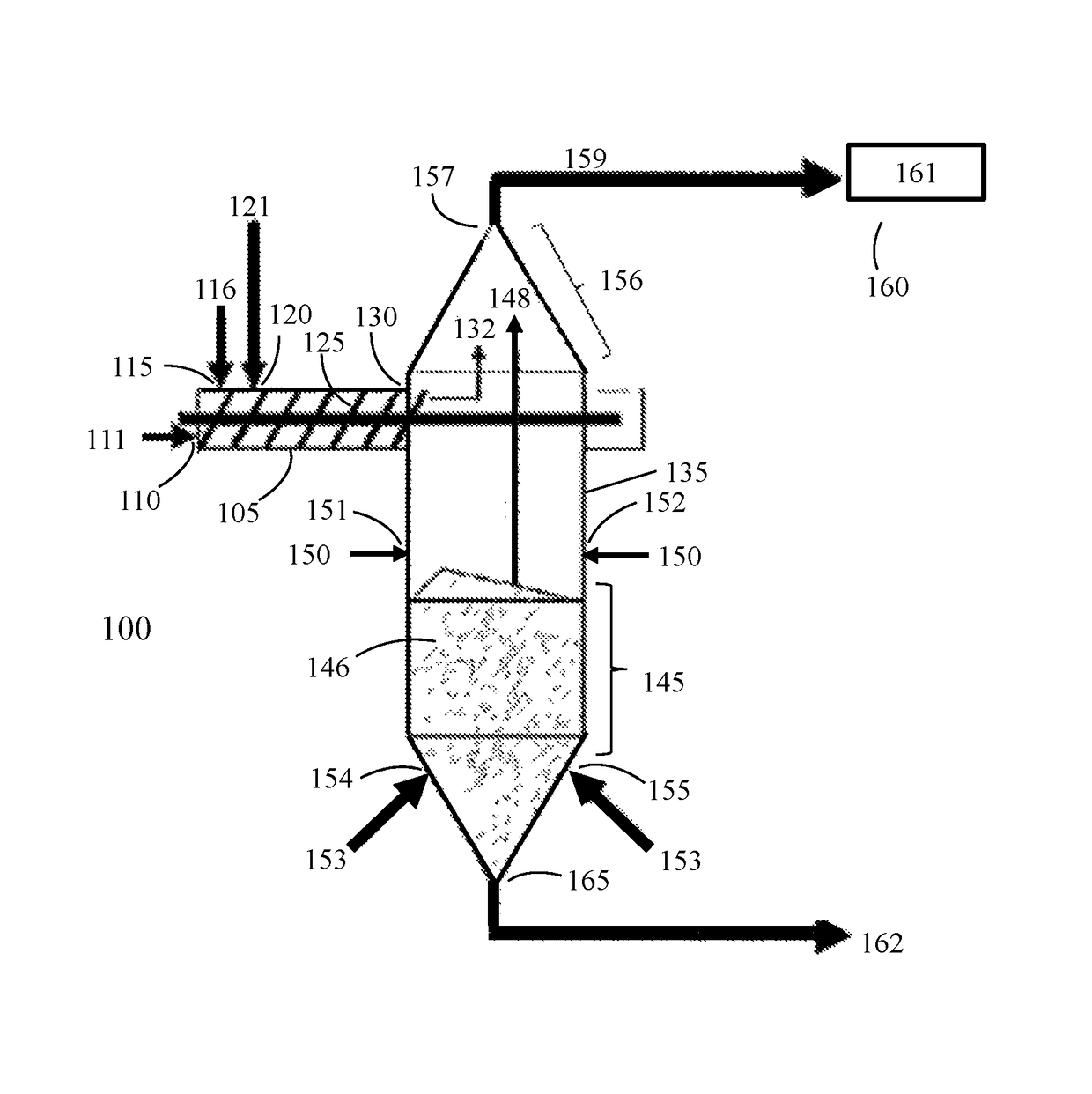
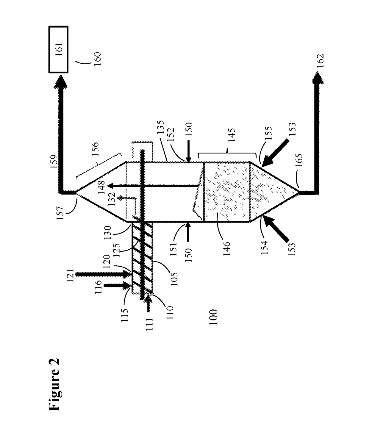
[0029]The inventive processes disclosed below partly relate to processes and systems for pyrolyzing a lignocellulosic biomass feedstock in a pyrolysis reactor comprising two reactor stages. The inventive processes and systems provide multiple pyrolysis residence times for more efficient pyrolysis of the different molecular components within a lignocellulosic feedstock. In certain embodiments, each reactor stage conducts pyrolysis at a different temperature to further maximize the efficiency of cellulosic biomass conversion into products that are suitable for use as a liquid hydrocarbon transportation fuel, fuel component, or mixtures thereof.

[0030]Examples of biomass feedstock used in the present invention include, but are not limited to lignocellulosic biomass, which is available from a variety of sources including forest residues, dead trees, branches, leaves, tree stumps, yard clippings, wood chips, wood fiber, sugar beets, miscanthus, switchgrass, hemp, corn, corn fiber, poplar,...


PUM

PropertyMeasurementUnit
temperatureaaaaaaaaaa
residence timeaaaaaaaaaa

Abstract

The present disclosure relates generally to two-stage biomass pyrolysis systems configured to maximize pyrolysis vapor yield from a lignocellulosic biomass while being conducive to commercial-scale throughput of lignocellulosic biomass. The system includes a reactor first stage comprising at least one auger pyrolyzes a lignocellulosic feedstock at a temperature and residence time that produces pyrolysis vapors derived predominantly from cellulose and hemi-cellulose fractions of the feedstock. A reactor second stage is configured to partially-pyrolyzed feedstock from the reactor first stage at a higher temperature for an additional residence time to produce additional pyrolysis vapors that are predominantly derived from of lignin. Certain embodiments arrange multiple reactor first stages around a single reactor second stage.

Description

CROSS-REFERENCE TO RELATED APPLICATIONS[0001]This application is a non-provisional application which according to 35 U.S.C. § 119(e) claims the benefit of, and the right of priority to, U.S. Provisional Application Ser. No. 62 / 298,568, filed Feb. 23, 2016, titled “Systems for Two-Stage Biomass Pyrolysis,” which is incorporated herein in its entirety, as permitted under 37 CFR 1.57(b).STATEMENT REGARDING FEDERALLY SPONSORED RESEARCH OR DEVELOPMENT[0002]None.FIELD OF THE INVENTION[0003]This invention relates to systems for pyrolysis of organic matter into useful chemical or fuel products.BACKGROUND[0004]Conventional fast pyrolysis of biomass entails rapid heating of a biomass feedstock in a hypoxic environment to produce a combination of non-condensable gases (C1-C4), condensable pyrolysis vapors and solid carbonaceous char. Conventional fast pyrolysis of biomass typically mixes biomass with a heated solid particles (i.e., “heat carrier”) to facilitate rapid heating of the biomass to ...

Claims


Application Information

Patent Timeline
Patent Type & Authority Patents(United States)
IPC IPC(8): B01J8/10C10B53/02C10C5/00B01J8/00C10B49/16B01J8/08
CPCB01J8/10B01J8/005B01J8/0045C10C5/00B01J8/087C10B49/16C10B53/02B01J8/082Y02P20/145Y02E50/10
Inventor DALLUGE, DUSTIN L.LUSK, STEVEN E.JONES, SAMUEL T.GORKE, JOHNATHAN T.
Owner PHILLIPS 66 CO
Features
  • R&D
  • Intellectual Property
  • Life Sciences
  • Materials
  • Tech Scout
  • Unparalleled Data Quality
  • Higher Quality Content
  • 60% Fewer Hallucinations
Learn More