Optical navigation systems and methods for background light detection and avoiding false detection and auto-movement

a technology of optical navigation and background light, applied in the field of optical navigation systems, can solve the problems of limiting the usefulness of ons in environments with strong background light, surface detection and light-induced motion, and limiting etc., to achieve the effect of reducing the usefulness of ons, reducing the cost, and reducing the cost of operation

Active Publication Date: 2018-03-27
CYPRESS SEMICON CORP
View PDF22 Cites 41 Cited by
  • Summary
  • Abstract
  • Description
  • Claims
  • Application Information

AI Technical Summary

Benefits of technology

[0021]In one embodiment, the false surface detection and light-induced motion reporting may be mitigated by incorporating light-blocking baffles (not shown) to OFN system SO, in an attempt to block background light 120, so that only light (preferably reflected from a tracking surface) from a particular angle or location would propagate upon optical detector 108. However, baffles may not completely block background light 120 because a portion of background light 120 may still be able to leak around tracking surface 106 or blocking baffles and inevitably transmitted through top panel 110 of OFN system 50. Also, if tracking surface 106 is not present, background light 120 may pass through without being blocked. In one alternative embodiment, static and dynamic data about the detected light is collected, and is subsequently compared to signatures that tend to be correlated with captured images of background light 120. However, in certain embodiments, only limited data static and dynamic data is available from optical detector 108 or sensor circuit, and the determination of background light 120 vs. desired reflected / scattered light 114 may be only partially effective. Occasionally background light 120 may be treated as desired reflected / scattered light 114, and vice-versa. Also the data collection and processing may take too much time and result in latency in reporting data to OFN system's SO users. In yet another embodiment, a capacitive sensing element 111 may be incorporated around or close or adjacent to OFN system 50, and use a capacitive sense detector to initiate surface tracking only if the capacitive sense detector has determined presence of a tracking surface 106, such as a finger. The capacitive sensing incorporated embodiment may require additional mechanical structure for capacitive sensing, complicates industrial design and increases cost. It may fail when tracking surface 106 is only in contact of the capacitive sense element but does not cover an effective optical tracking area of OFN system 50.
[0032]In one embodiment, the concept of optical sensing during a switching-off period of light (EM radiation) source may be adapted to infrared proximity detection modules, such as the modules used in cellular phones or tablets. It may also improve performance of infrared proximity sensors by reducing occurrence of false detection.

Problems solved by technology

One of the problems with existing OFN systems is that the ONS, in particular the optical sensors, may not differentiate between light reflected or scattered off a finger or stylus and environmental or ambient light.
Sunlight is a particular problem especially for OFN systems installed in vehicles, and manufacturers usually require that the OFN systems pass strict sunlight tests with specified range of light intensity conditions, test time, test angle, and orientations relative to sunlight.
Both of these potential failures—false surface detection and light-induced motion are observed, and limit the usefulness of ONS in environments that have strong background light 120.
However, in certain embodiments, only limited data static and dynamic data is available from optical detector 108 or sensor circuit, and the determination of background light 120 vs. desired reflected / scattered light 114 may be only partially effective.
Also the data collection and processing may take too much time and result in latency in reporting data to OFN system's SO users.
The capacitive sensing incorporated embodiment may require additional mechanical structure for capacitive sensing, complicates industrial design and increases cost.
It may fail when tracking surface 106 is only in contact of the capacitive sense element but does not cover an effective optical tracking area of OFN system 50.
However, in the event that background light 120 is determined absent, there may be missing motion data during the light-off period as optical detector 108 may fail to sense any reflected / scattered light 114, resulting in missing tracking surface 106 motion data.
As such, debouncing or taking an average of multiple light-off data may not help mitigate the potential sensing errors.

Method used


Image

  • Optical navigation systems and methods for background light detection and avoiding false detection and auto-movement
  • Optical navigation systems and methods for background light detection and avoiding false detection and auto-movement
  • Optical navigation systems and methods for background light detection and avoiding false detection and auto-movement

Examples


Embodiment Construction

[0013]The following description sets forth numerous specific details such as examples of specific systems, components, methods, and so forth, in order to provide a good understanding of several embodiments of the subject matter. It will be apparent to one skilled in the art, however, that at least some embodiments may be practiced without these specific details. In other instances, well-known components or methods are not described in detail or are presented in a simple block diagram format in order to avoid unnecessarily obscuring the techniques described herein. Thus, the specific details set forth hereinafter are merely exemplary. Particular implementations may vary from these exemplary details and still be contemplated to be within the spirit and scope of the embodiments.

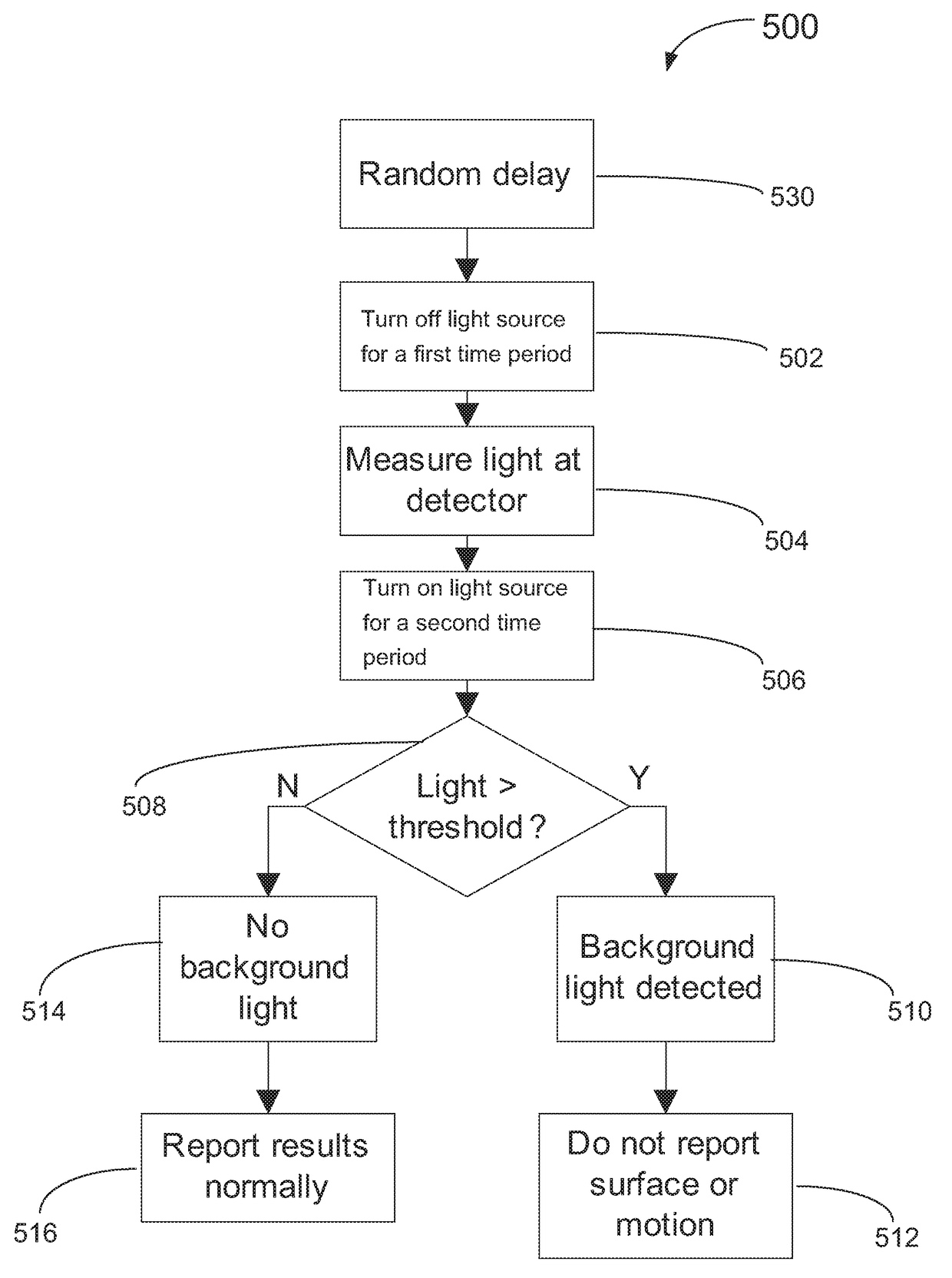
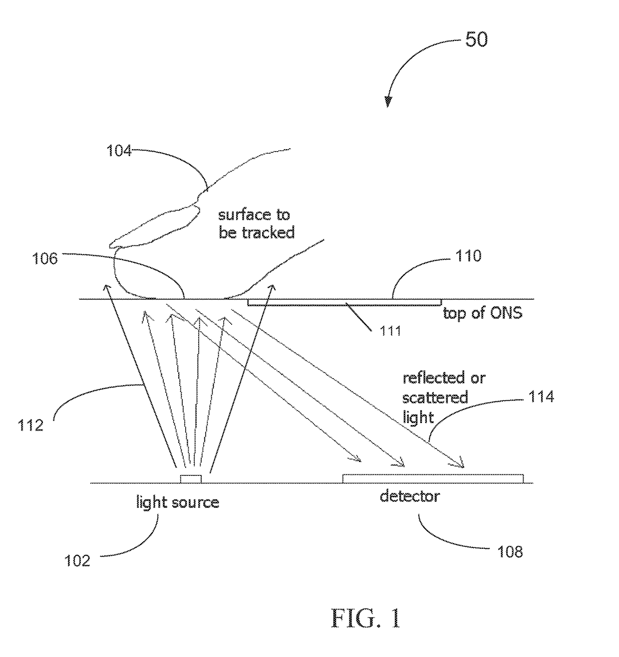
[0014]Embodiments of the optical finger navigation (OFN) system and optical navigation sensor (ONS), and methods of operating the same to at least mitigate incidents of false surface detection and inaccurate tra...


PUM


Abstract

A method of operating an optical navigation system which includes disabling a light source to measure the ambient or external light level, comparing the measurement to a threshold level to determine whether the ambient light would cause false detection and light induced motion, and adjusting sensing parameter(s) to mitigate the effect of the ambient light.

Description

PRIORITY[0001]The present application claims the priority and benefit under 35 U.S.C. § 119(e) of U.S. Provisional Application No. 62 / 055,803, filed on Sep. 26, 2014, which is incorporated by reference herein in its entirety.TECHNICAL FIELD[0002]The present disclosure relates generally to the field of optical navigation systems, and more particularly to optical finger navigation systems and methods of operation therefor to distinguish external background light for improved navigation surface detection and motion tracking.BACKGROUND[0003]Optical finger navigation (OFN) modules or systems make use of optical physics to measure the degree of the relative motion, in both speed and magnitude, between a navigation device and the navigation / tracking surface. These OFN systems find their major application in pointing and finger tracking devices and are becoming increasingly common in data processing systems, such as cellular telephones, tablet computers, electronic readers, control pad / cons...

Claims


Application Information

Patent Timeline
Patent Type & Authority Patents(United States)
IPC IPC(8): G06F3/041G06F3/042G06F3/044G06F3/0354G06F1/32
CPCG06F3/0418G06F1/3231G06F1/3262G06F3/03547G06F3/044G06F3/0421G06F3/042Y02D10/173G06F2203/04106G06F3/04186Y02D10/00
Inventor FRAME, JOHNMU, JING
Owner CYPRESS SEMICON CORP
Why Eureka
Try Eureka