All-suture suture anchor systems and methods

a suture anchor and all-suture technology, applied in the field of all-suture suture anchor systems and methods, can solve the problems of anchor sharing the same weakness of relying on friction, damage to the articulating surface, and slippag

Active Publication Date: 2018-04-24
CAYENNE MEDICAL INC
View PDF7 Cites 4 Cited by
  • Summary
  • Abstract
  • Description
  • Claims
  • Application Information

AI Technical Summary

Benefits of technology

[0007]The following disclosure describes the design for a novel all-suture suture anchor together with the associated delivery accessories and methods which are intended to secure tissue to bone. The all-suture anchor eases this concern and gives surgeons piece of mind, because when an all suture anchor pulls out, there is only a piece of soft suture left in the joint.

Problems solved by technology

That piece of material could temporary or permanently be stuck within the joint, causing damage to the articulating surfaces.
The technique for using the anchor is also very similar as the company suggests in its own words: “Drill Pilot Hole, Insert Anchor, and Pull-to set.” Since the anchor designs and techniques are similar, the anchor shares the same weakness of relying on friction.
Thus, slippage can occur, and pull out strength could not be adequate.
However, such claimed expansion dimensions are theoretical only, because the soft suture is not stiff enough to penetrate the hole to achieve such dimensions in practice.

Method used


Image

  • All-suture suture anchor systems and methods
  • All-suture suture anchor systems and methods
  • All-suture suture anchor systems and methods

Examples


Embodiment Construction

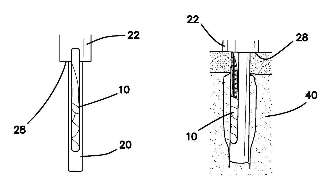
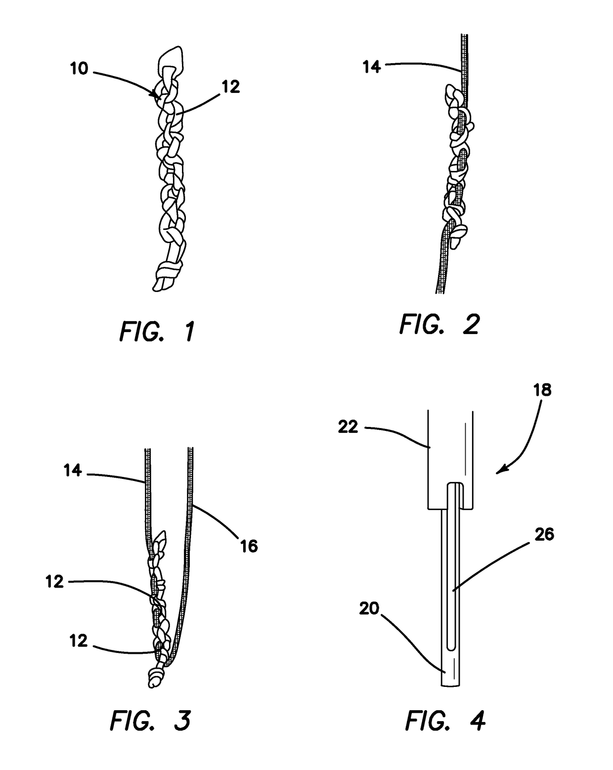
[0047]Referring now more particularly to the drawings, there is shown in FIG. 1 a suture anchor 10 comprised entirely of a suture material. In the illustrated embodiment, the anchor 10 includes eight connected suture links 12. The linkage 10, formed of the links 12, is created by tying two alternating half hitches using two strands of #2 high strength suture. The two suture strands continue to form a small loop, then followed by two alternating half hitches. As shown in FIG. 2, a preloaded suture 14 is woven through the links or loops 12 on the anchor 10 to make a complete anchor assembly. As shown in FIG. 3, a tensioning suture limb 16 extends from one end of the anchor 10.

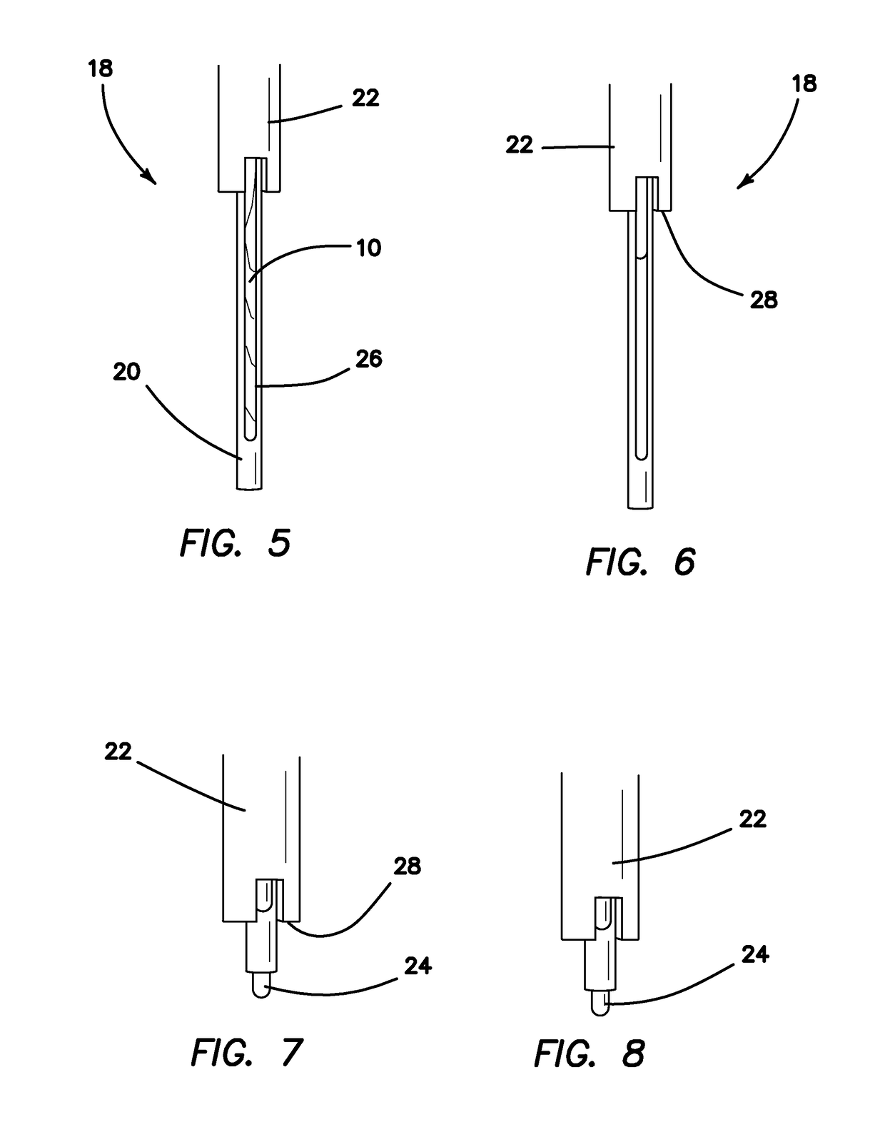
[0048]Now with reference to FIGS. 4-9, in particular, details of an inserter 18 for use in the inventive system are shown. The inserter 18 comprises three main elements. These elements include an inserter distal end 20 (FIGS. 4 and 5), an outer tube 22 (FIGS. 6-8), and an internal push rod 24 (FIGS. 8 and 9). The...


PUM


Abstract

An all-suture suture anchor system includes an all-suture anchor, an inserter, and a specially designed drill. The drill is used to enlarge the hole and create a pocket under the bone surface from the pre-drilled hole. The created pocket is intended to accommodate the expansion of the anchor when deployed into the bone, generating a true mechanical interference under the bone surface. The anchor is loaded on the inserter and placed at full length vertically inside the drilled hole. While holding the inserter on top of the drilled hole, so that a feature on the inserter keeps the anchor to a desired depth below the bone surface, tension is applied to the suture limb that is connected to the bottom end of the anchor. This tensioning step causes the length of the anchor to contract vertically and the anchor is simultaneously expanded circumferentially to fill the pocket previously created by the drill. Since the pocket created by the drill is intended to contain the deployed anchor, the deployed position of the anchor is consistently predictable.

Description

[0001]This application claims the benefit under 35 U.S.C. 119(e) of the filing date of Provisional U.S. Application Ser. No. 61 / 923,591, entitled All-Suture Suture Anchor, filed on Jan. 3, 2014, which application is herein expressly incorporated herein by reference, in its entirety.BACKGROUND OF THE INVENTION[0002]There are many soft-tissue to bone repair procedures, such as rotator cuff, SLAP and Bankart lesion repairs, or reconstruction of labral tissue to the glenoid rim, in which a surgeon needs to secure tissue in close contact with bone by implanting an anchor, pre-loaded with suture, into a hole drilled in the bone at the desired anchor location. Commonly, the anchor which the sutures are attached to is made of either plastic such as PEEK or metal such as Titanium or Stainless Steel. In the case of an implant pulling out of the bone there is a piece of hard material from that implant floating inside the joint space. That piece of material could temporary or permanently be stu...

Claims


Application Information

Patent Timeline
Patent Type & Authority Patents(United States)
IPC IPC(8): A61B17/04A61B17/16A61B17/06
CPCA61B17/0401A61B17/1615A61B17/06166A61B2017/0409A61B17/1617A61B2017/0406
Inventor NGUYEN, HOANG P.HARPER, DEREK J.BAIRD, KEVIN N.
Owner CAYENNE MEDICAL INC
Why Eureka
Try Eureka