
Device for coating parts including a movable receiver in which a dispenser device and an IR emitter device are located

a technology of a dispenser device and a receiver is applied in the field of small parts coating devices, which can solve the problems of large time requirements and inefficiency of coating with such a devi

Active Publication Date: 2018-04-24
SPECIAL COATINGS
View PDF94 Cites 0 Cited by
  • Summary
  • Abstract
  • Description
  • Claims
  • Application Information

AI Technical Summary

Benefits of technology

[0003]Therefore, it is an object of the present invention to overcome the disadvantages of the known devices, and in particular, to provide a device and a process, allowing a fast and economical coating of small parts, in particular mass produced small parts with a high surface quality. In particular, also all possible geometries of small parts, part of which cannot be coated with the known device, are to be coated in an efficient manner.
[0004]An aspect of the invention is characterized in that the drying and / or the hardening is performed through radiation energy in a device or a process, in which the small parts to be coated are provided with coating material during a motion, like, e.g., a constant turning over or shaking. In particular, infrared (IR) emitters and / or ultraviolet (UV) emitters can be used as energy emitters, since with these a fast and even heating of the parts to be coated and / or a hardening of the coating material, like, e.g., UV hardening lacquer, is facilitated. Furthermore, such energy emitters are easy to operate and / or control, or regulate, which simplifies the coating process further, allowing an efficiency increase. In particular, a significant shortening of the warm up or start up time can be observed, which is necessary e.g., in order to bring the small parts to be coated to a minimum temperature required for the coating. Furthermore, overall, through the fast and even hardening of the deposited coating material, a significantly improved layer quality and surface quality is accomplished in comparison to the state of the art. As a further advantage, bodies with any geometry can be coated, which cannot be coated satisfactorily with the state of the art technology.
[0006]The movement of the small parts can be performed through receiving them in a rotating drum, which has transport ribs, in particular facilitating the turning over of the small parts in the drum through the rotating motion. Besides the rotating motion of a drum, also further types of devices for motion generation are suitable, allowing a continuous or constantly repeating motion of the small parts. In particular, shaking and rattling apparatuses are suitable.
[0009]The coating device, besides allowing the continuous dispensing of small amounts of coating material, also allows the dispensing of extremely small amounts of coating material in intermittent small portions, so that thereby also an instant drying and / or hardening can be made possible.
[0013]According to one of several embodiments, the ventilation openings are disposed with their spouts at one or several closure elements or covers, closing the receiving cavity of the receiving element, e.g., of a drum, so that they can be removed from the receiving cavity, when the receiving element is opened. Accordingly, also the IR emitter devices and / or the dispensing devices, e.g. the spray gun, can be disposed at one or several closing elements so that the at least one IR radiation emitter device and / or the at least one dispenser device is configured to be moved into and out of a receiving area of the movable receiver element through operating the at least one closing element. This allows a simple emptying and cleaning of the receiving element. The pivot motion range of the receiving element according to another preferred embodiment also serves this purpose.

Problems solved by technology

This, however, requires a large amount of time, so that coating with such a device is not efficient.

Method used


Image

  • Device for coating parts including a movable receiver in which a dispenser device and an IR emitter device are located
  • Device for coating parts including a movable receiver in which a dispenser device and an IR emitter device are located
  • Device for coating parts including a movable receiver in which a dispenser device and an IR emitter device are located

Examples


Embodiment Construction

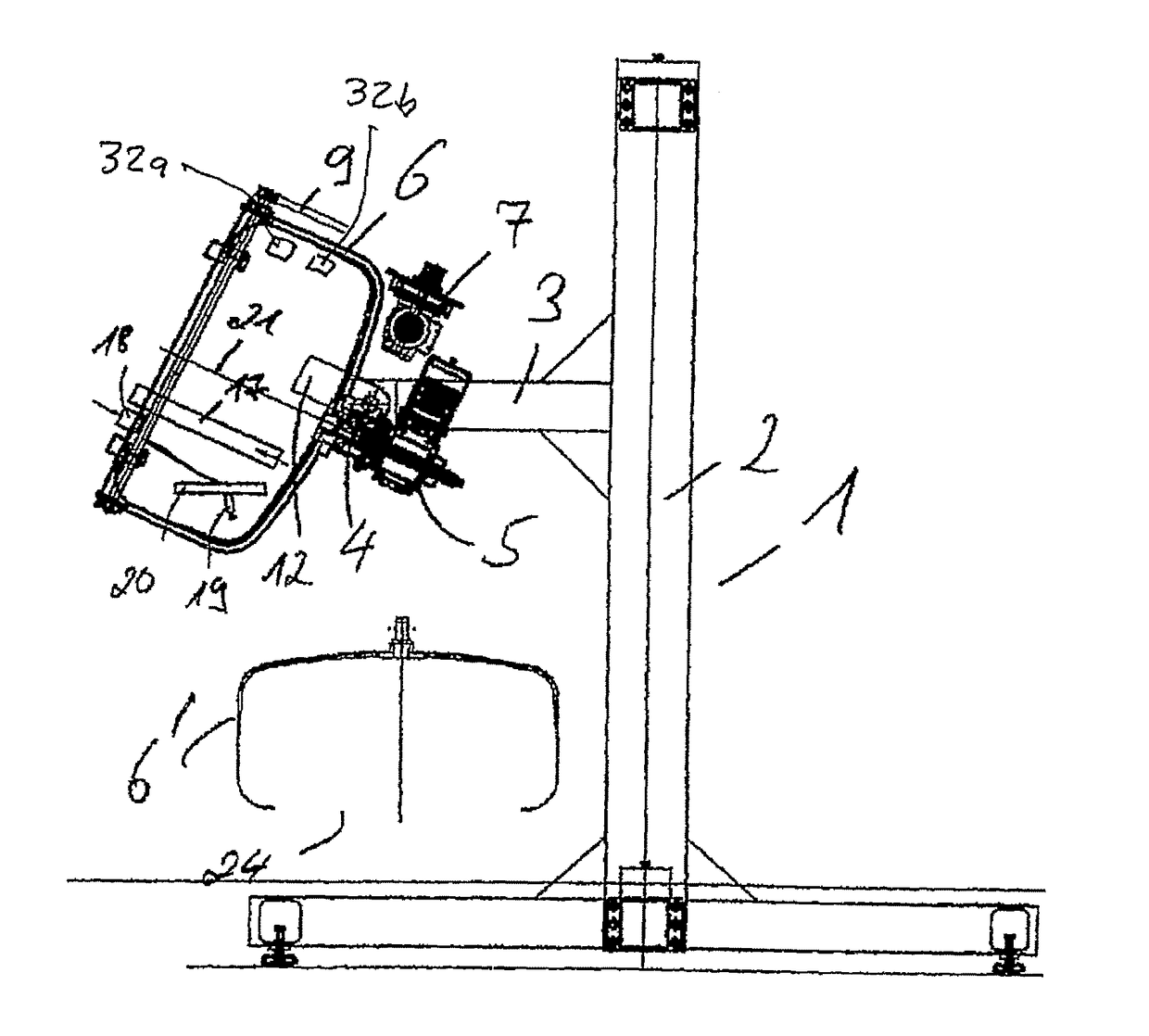
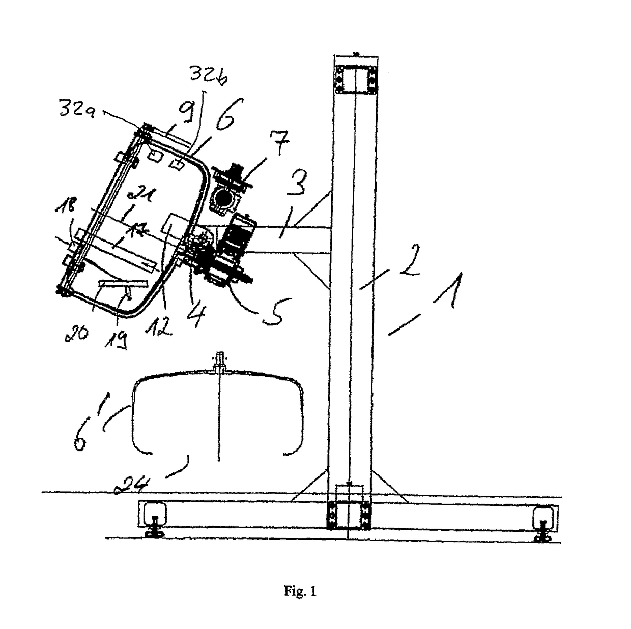
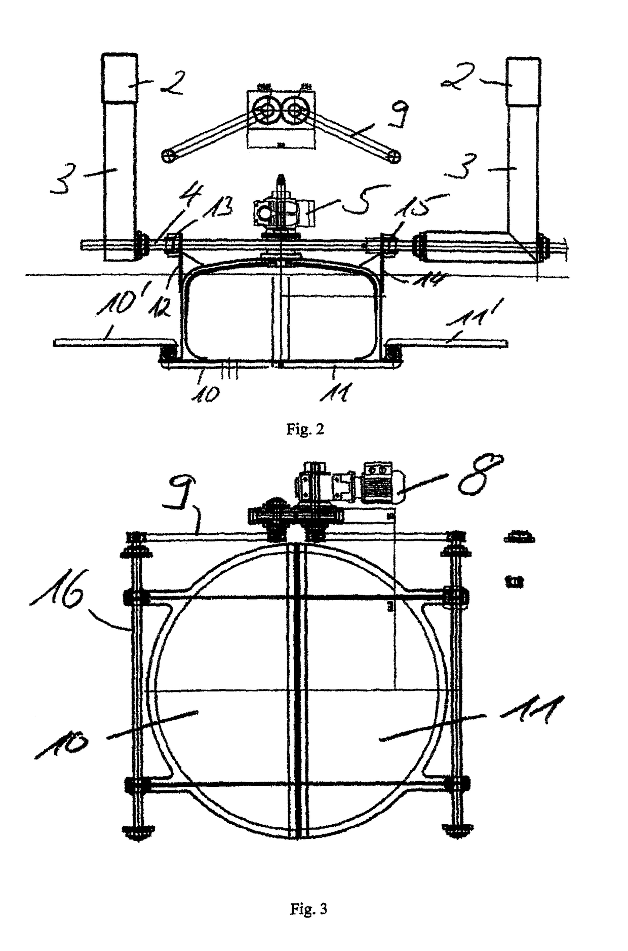
[0019]FIG. 1 shows a lateral sectional view of a device 1, according to the invention, in which, as can be seen in particular from FIG. 2, a drum 6, rotatable around an axis 21, is pivotably mounted to a frame with two vertical pillars 2 and horizontal pillars 3, mounted thereupon, receiving the small parts 23 (see FIG. 4). Between the horizontal beams 3, a rod 4 is provided, on which the drum 6 is pivotably mounted through the mounting flanges 12 and 14 and the pivot supports 13 and 15, and thus in a position 6′, as shown in FIG. 1. Through pivoting around the rod 4, or its longitudinal axis into the position 6′, the drum 6 can be emptied in a simple manner. For pivoting, a drive in the form of an electric motor 7 is provided.

[0020]Besides the pivoting ability around the rod 4, the drum is rotatable around the axis 21, wherein an electric motor 5 is provided as a rotations drive for this purpose.

[0021]The drum 6 has a closure provided as two closure flaps 10, 11 at the drum opening...


PUM

PropertyMeasurementUnit
wavelengthaaaaaaaaaa
temperatureaaaaaaaaaa

Abstract

The present invention relates to a coating device for small parts, in particular for lacquering mass produced small parts, like e.g. bolts, small plastic parts and similar, and it relates to a method for this purpose with a movable receiver element for receiving and moving the small parts, and a dispenser device, located at the receiver element for continuous or portioned dispensing the coating material into the receiver element, wherein a radiation emitter device is provided in the receiver element for emitting radiation for drying and / or hardening the coating material.

Description

TECHNICAL FIELD[0001]The present invention relates to a method and a device for coating small parts, in particular mass produced small parts, like bolts, small plastic parts, or similar.STATE OF THE ART[0002]From the Patent document DE 85 24 347 U1, a device for coating small parts, in particular pharmaceuticals, is known, including a rotating drum and a spray gun disposed in the interior of the drum for distributing the coating material. Such a device is also used for lacquering small parts, wherein the lacquer is dried through warm air, which is run through the drum. Through turning the small parts over during the coating process, it is assured that the coating material or the lacquer is distributed evenly onto all small parts. In order to avoid damaging the coating, which has not dried or hardened yet, through the motion of the small parts and the associated collisions, the small parts have to be at a certain minimum temperature, allowing a quick drying of the lacquer, or of the ...

Claims


Application Information

Patent Timeline
Patent Type & Authority Patents(United States)
IPC IPC(8): B05B13/02B05C11/10B05C3/05A61J3/06A23G3/26B01J2/12
CPCB05B13/0257B05C3/05B05C11/1015B05C11/1034B05D2258/00A23G3/26A61J3/06B01J2/12
Inventor BRENDEL, GERHARD
Owner SPECIAL COATINGS
Learn More