Solar thermal power generation system

a technology of solar energy and power generation system, which is applied in the field of solar energy power generation system, can solve the problems of increasing the construction cost affecting the efficiency of solar energy generation plant, so as to achieve the effect of reducing construction cost and power generation cost, simplifying the system of solar energy power generation plant, and reducing construction cos

Active Publication Date: 2018-05-01
MITSUBISHI POWER LTD
View PDF27 Cites 0 Cited by
  • Summary
  • Abstract
  • Description
  • Claims
  • Application Information

AI Technical Summary

Benefits of technology

[0013]The object of the present invention, which has been made in consideration of the above-described situation, is to simplify systems in the solar thermal power generation plant and thereby provide a solar thermal power generation system achieving reduction in the construction cost and the power generation cost.
[0015]According to the present invention, systems in the solar thermal power generation plant can be simplified and a solar thermal power generation system achieving reduction in the construction cost and the power generation cost can be provided.

Problems solved by technology

Thus, there is apprehension about complication of the switching system employing the three valves and complication of the operation such as the switching control.
Thus, installation of four types of heat exchangers (steam heat exchanger 33, saturated steam condenser 34, saturated water heat exchanger 35, saturated water evaporator 38) becomes necessary and the heat accumulation / radiation system is necessitated to be complicated, leading to a rise in the construction cost of the solar thermal power generation plant.
Thus, also in this case, installation of multiple heat exchangers (feed-water preheater, evaporator, superheater, reheater) compatible with the phase change phenomena becomes necessary, the system is complicated, and the construction cost rises.

Method used


Image

  • Solar thermal power generation system
  • Solar thermal power generation system
  • Solar thermal power generation system

Examples


first embodiment

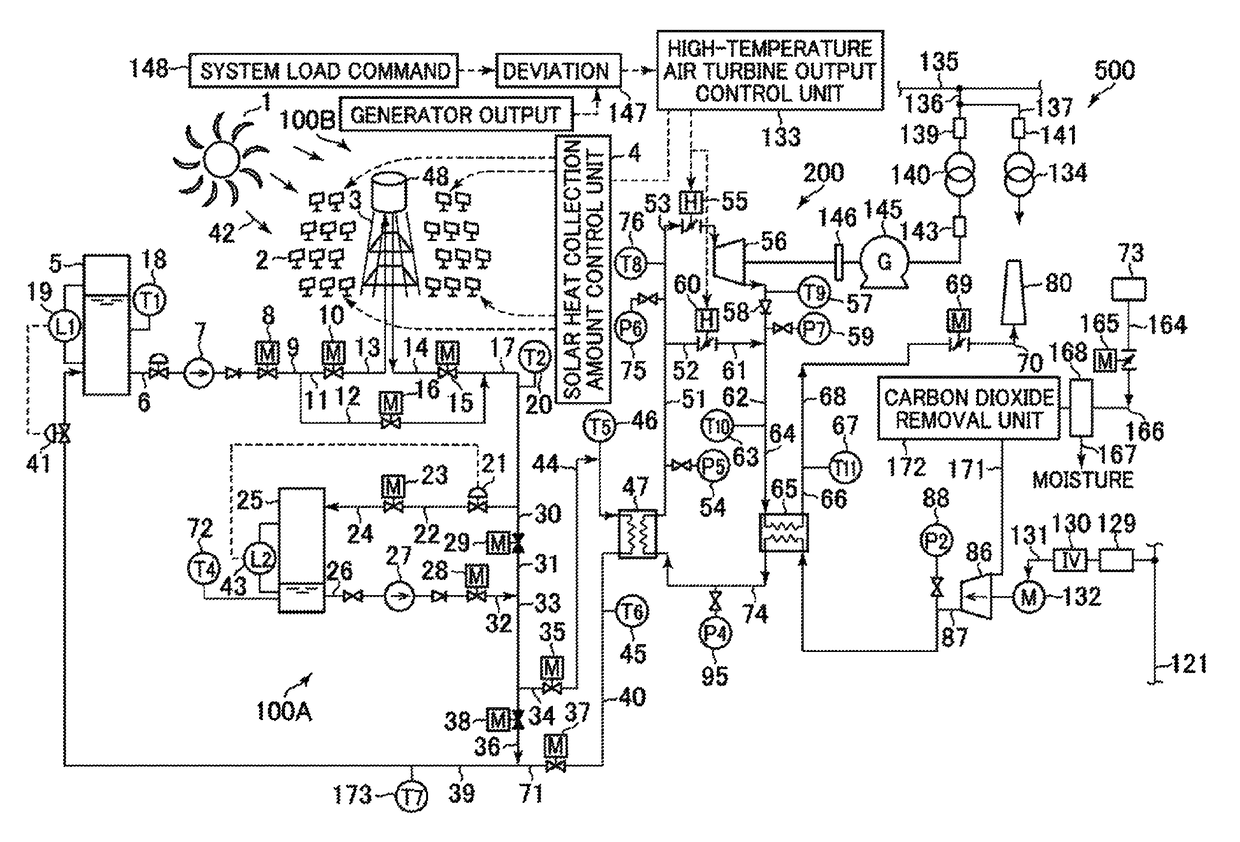
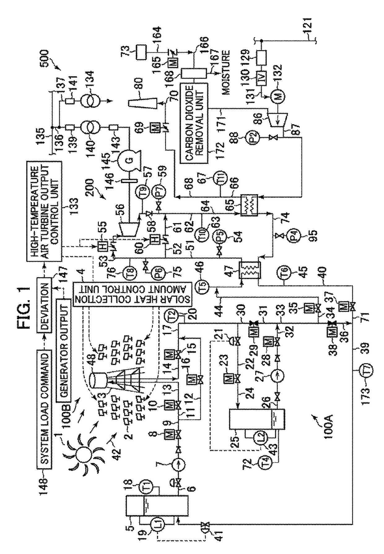
[0031]FIG. 1 is a conceptual diagram showing the configuration of a first embodiment of the solar thermal power generation system according to the present invention.

[0032]In FIG. 1, the solar thermal power generation system comprises a solar heat accumulation / radiation device 100A constituting the primary system, a solar heat collection device 100B also constituting the primary system, and a compressor / high-temperature turbine power generation device 200 constituting the secondary system.

[0033]The solar heat accumulation / radiation device 100A is mainly composed of a primary low-temperature heat medium tank 5, a primary low-temperature heat medium pump 7, a primary high-temperature heat medium tank 25, a primary high-temperature heat medium pump 27, and a secondary heat medium heater 47. The primary low-temperature heat medium tank 5 stores a low-temperature primary heat medium. The primary low-temperature heat medium pump 7 sends out the primary heat medium from the primary low-temp...

second embodiment

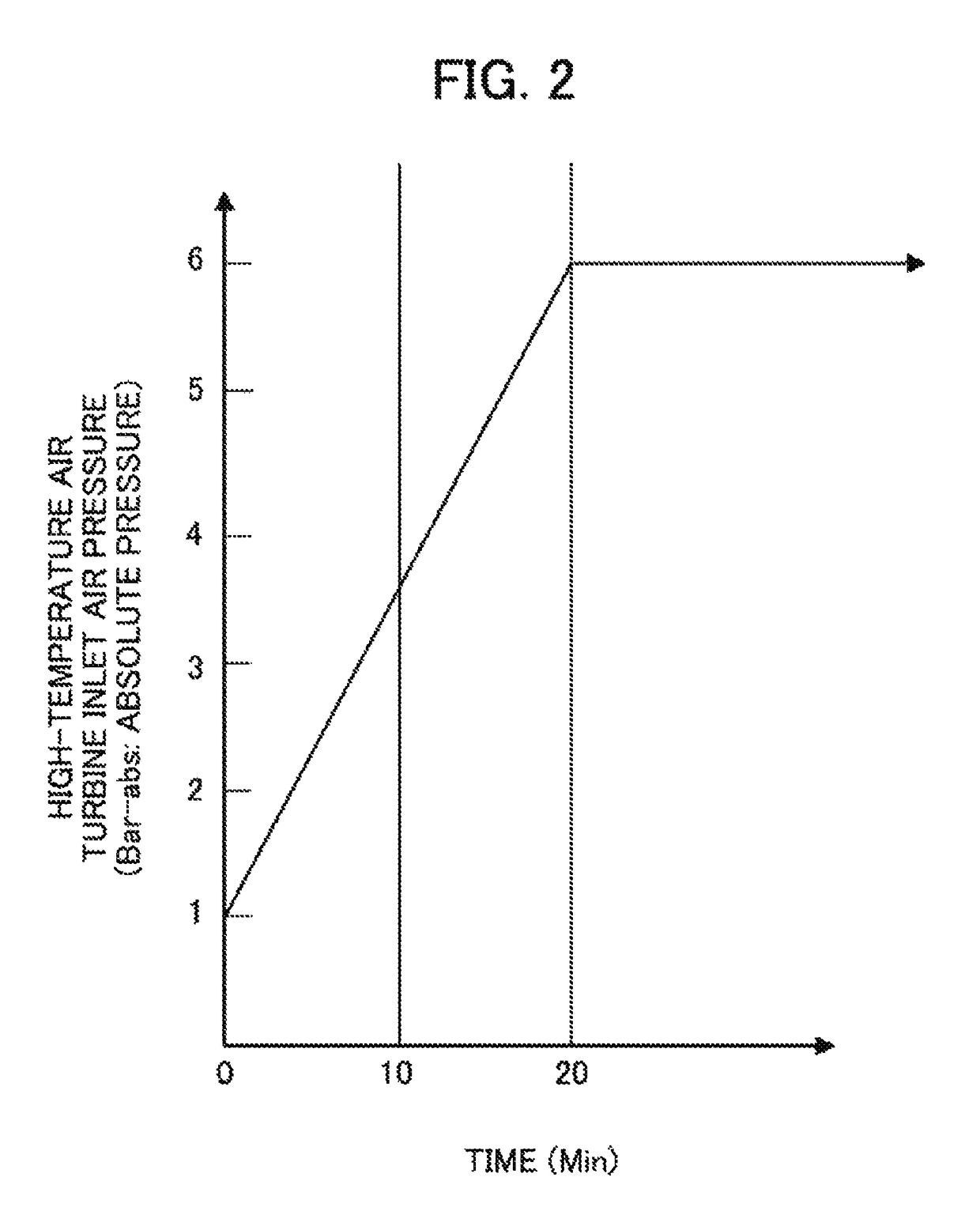
[0086]A second embodiment of the solar thermal power generation system according to the present invention will be described below with reference to figures. FIG. 5 is a conceptual diagram showing the configuration of the second embodiment of the solar thermal power generation system according to the present invention. FIG. 6 is a characteristic conceptual diagram showing the characteristics of the high-temperature air turbine inlet pressure with respect to the startup time of the compressor in the second embodiment of the solar thermal power generation system according to the present invention. Reference characters in FIGS. 5 and 6 identical with those in FIGS. 1-4 represent elements equivalent to those in FIGS. 1-4, and thus detailed explanation thereof is omitted for brevity.

[0087]In the second embodiment of the solar thermal power generation system according to the present invention, the configuration of the solar thermal power generation system is basically equivalent to that in...


PUM


Abstract

The object is to simplify systems in a solar thermal power generation plant and thereby provide a solar thermal power generation system achieving reduction in the construction cost and the power generation cost. The solar thermal power generation system comprises: a solar heat collection device which collects solar heat and thereby heats up molten salt as a primary heat medium; a solar heat accumulation / radiation device including a low-temperature tank which stores molten salt to be supplied to the solar heat collection device, a high-temperature tank which stores high-temperature molten salt heated by the solar heat collection device, and a secondary heat medium heater which heats up a secondary heat medium by using the high-temperature molten salt supplied from the high-temperature tank as a heating medium; and a compressor / high-temperature turbine power generation device including a compressor which generates compressed air as the secondary heat medium by compressing air taken in from the atmosphere to a prescribed pressure and a high-temperature air turbine which drives a generator by taking in the compressed air heated by the secondary heat medium heater.

Description

BACKGROUND OF THE INVENTION[0001]1. Field of the Invention[0002]The present invention relates to a solar thermal power generation system.[0003]2. Description of the Related Art[0004]As an example of a solar thermal power generation plant capable of efficiently accumulating solar heat, there exists a solar thermal power generation plant comprising a solar heat collection device which generates superheated steam by using water / steam (water vapor) as the primary heat medium, a solar heat accumulation / radiation device which uses molten salt or oil as the solar heat accumulation / radiation heat medium, and steam turbine power generation equipment which uses steam (water vapor) as the secondary heat medium (see JP-2014-92086-A, for example).[0005]There also exists a solar thermal power generation plant comprising a high-temperature molten salt tank which stores high-temperature molten salt supplied from a heat collector by using molten salt as the primary heat medium and the heat accumulat...

Claims


Application Information

Patent Timeline
Patent Type & Authority Patents(United States)
IPC IPC(8): B60K16/00F03G6/06F24V50/00
CPCF03G6/064Y02E10/465F02C1/05Y02E10/46Y02E10/50Y02A40/966
Inventor MISHIMA, NOBUYOSHINAGAFUCHI, NAOYUKI
Owner MITSUBISHI POWER LTD
Why Eureka
Try Eureka