
LED packages using highly reflective die attach material and enhanced reflective substrates

a technology of reflective substrates and die-attached packages, which is applied in the direction of basic electric elements, electrical equipment, semiconductor devices, etc., can solve the problems of reducing the life span of led devices, additional steps, and limiting the overall life span of led packages, so as to improve the long-term reliability of led packages, enhance reflective substrates, and reduce the effect of the reflectivity degradation of the substrate caused by led

Active Publication Date: 2018-05-01
LUMINUS INC
View PDF1 Cites 1 Cited by
  • Summary
  • Abstract
  • Description
  • Claims
  • Application Information

AI Technical Summary

Benefits of technology

The targeted application of die attach material to vulnerable areas based on temperature distribution models effectively prolongs the life span of LED packages by reducing heat-induced degradation, maintaining high performance and reliability while avoiding unnecessary coverage of reflective surfaces.

Problems solved by technology

However, the highly reflective substrate suffers from long-term reliability issues that reduce the life span of the LED device.
However, Ag is a material that can easily migrate, be oxidized, and thus tarnish during the operation.
However, all the protection techniques treat the whole substrate uniformly without considering different temperature distribution and its effects in different areas of the substrate and they require additional steps to protect the substrate.
These new protection technologies although prolongs the life span of the LED package, they fail to extend protections to the vulnerable areas, resulting in limiting the overall life span of the LED package.

Method used


Image

  • LED packages using highly reflective die attach material and enhanced reflective substrates
  • LED packages using highly reflective die attach material and enhanced reflective substrates
  • LED packages using highly reflective die attach material and enhanced reflective substrates

Examples


Embodiment Construction

[0018]Reference will now be made in detail to some embodiments of the invention, examples of which are illustrated in the accompanying drawings.

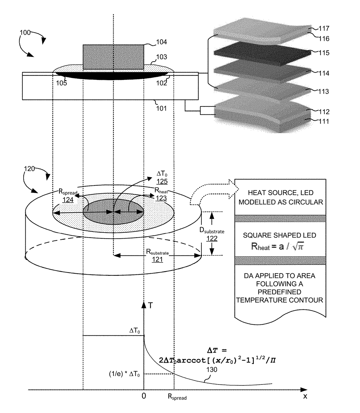
[0019]The exponential market growth drives the rapid technology advancements in the LED industry. Current technology focuses on extend the life span of the highly reflective silver layer by applying additional protection layers to the entire substrate. Such methods, although, successfully protect the ordinary tarnish of the silver layer in general, they fail to consider the heat effects generated by LED chips, which accelerates the degradation in specific area surrounding the LED chips. Further, covering the entire substrate with protection layer defeats the purpose of using highly reflective substrates in LED packages since the reflective surfaces are all covered and protected. The growing demands for LED lighting requires further improvements for the long-term reliability of LED devices. The current invention uses temperature distribution ...


PUM


Abstract

Methods and apparatus are provided to improve long-term reliability of LED packages using reflective opaque die attach (DA) material. In one novel aspect, a protected area surrounding edges of the LED is determined. The DA is applied to the determined protected area by a dispense process, a stamping process, or a screen printing process, such that the effect of temperature degradation is reduced. A heat distribution model is used to determine the protected area, which is between edges of the LED and a predefined isothermal line where the temperature is 1 / e that of the temperature at edges of the LED. In another embodiment, the protected area is further based on a spreading ratio of the substrate size to the LED size. In another novel aspect, with multiple LEDs in the LED package, the spreading ratio is further based on pitch distances to the immediate adjacent LEDs and the substrate boundary.

Description

CROSS REFERENCE TO RELATED APPLICATIONS[0001]This application claims priority under 35 U.S.C. § 119 from U.S. Provisional Application No. 62 / 040,370 entitled “RELIABLE LED PACKAGES USING HIGHLY REFLECTIVE DIE ATTACH MATERIAL AND ENHANCED AG SUBSTRATES,” filed on Aug. 21, 2014, the subject matter of which is incorporated herein by reference.TECHNICAL FIELD[0002]The present invention relates generally to light-emitting diodes (LEDs) and, more particularly, to LED packages using highly reflective die attach material and enhanced reflective substrates.BACKGROUND INFORMATION[0003]Development in light-emitting diode (LED) lighting technology continues to take place at a dramatic pace. With improved brightness, lower energy consumption and longer life spans, the global market for LED lighting has grown exponentially. The rapid adoption of LED lighting in the commercial and residential markets requires further improvements in LED efficiency and quality. One of the important measurements for...

Claims


Application Information

Patent Timeline
Patent Type & Authority Patents(United States)
IPC IPC(8): H01L29/18H01L33/46H01L33/64H01L33/60H01L25/075
CPCH01L33/60H01L25/0753H01L33/46H01L33/641H01L33/642H01L2924/0002H01L2933/0075H01L2933/0025H01L2933/0058H01L2924/00
Inventor SHAN, QIFENGMA, HONGTAOTONG, TAO
Owner LUMINUS INC
Learn More