
OLED device having enhancement layer(s)

a technology of organic light and enhancement layer, which is applied in the direction of semiconductor devices, photovoltaic energy generation, solid-state devices, etc., can solve the problems of reducing the efficiency roll-off reducing the efficiency of the oled device, and reducing the emission rate. , to achieve the effect of reducing the emission rate, reducing the aging rate of the emitter, and modifying the effective properties

Active Publication Date: 2018-05-01
UNIVERSAL DISPLAY
View PDF9 Cites 30 Cited by
  • Summary
  • Abstract
  • Description
  • Claims
  • Application Information

AI Technical Summary

Benefits of technology

The patent describes a method for improving the operation of OLED displays by using a special layer called an enhancement layer. This layer contains a material that resonates with the organic material in the OLED display, allowing for better transfer of energy. The method involves maximizing the transfer of energy through a process called surface plasmon resonance. The enhancement layer can be placed at different locations in the OLED display to achieve different effects such as reduced emission, modification of emission line-shape, change in intensity, and increased efficiency. Overall, the patent provides a way to improve the performance of OLED displays.

Problems solved by technology

The enhancement layer modifies the effective properties of the medium in which the organic fluorophore or phosphorescent molecule resides resulting in any or all of the following: a decreased rate of emission, a modification of emission line-shape, a change in emission intensity with angle, a change in aging rate of emitter, and reduced efficiency roll-off of the OLED device.

Method used


Image

  • OLED device having enhancement layer(s)
  • OLED device having enhancement layer(s)
  • OLED device having enhancement layer(s)

Examples


Embodiment Construction

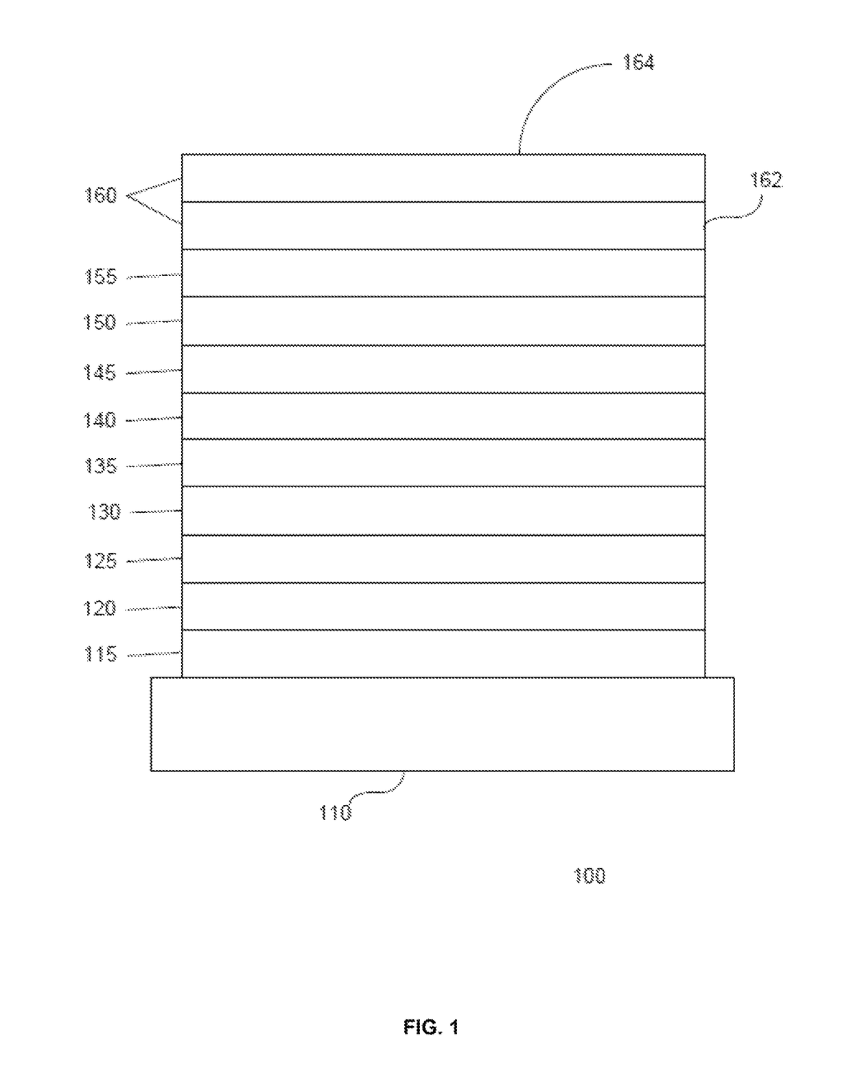
[0045]Generally, an OLED comprises at least one organic layer disposed between and electrically connected to an anode and a cathode. When a current is applied, the anode injects holes and the cathode injects electrons into the organic layer(s). The injected holes and electrons each migrate toward the oppositely charged electrode. When an electron and hole localize on the same molecule, an “exciton,” which is a localized electron-hole pair having an excited energy state, is formed. Light is emitted when the exciton relaxes via a photoemissive mechanism. In some cases, the exciton may be localized on an excimer or an exciplex. Non-radiative mechanisms, such as thermal relaxation, may also occur, but are generally considered undesirable.

[0046]The initial OLEDs used emissive molecules that emitted light from their singlet states (“fluorescence”) as disclosed, for example, in U.S. Pat. No. 4,769,292, which is incorporated by reference in its entirety. Fluorescent emission generally occur...


PUM


Abstract

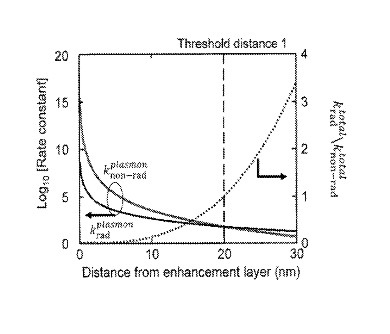
A method for improving the operation of an OLED includes maximizing on-radiative transfer of excited state energy from the OLED's organic emissive material to surface plasmon polaritons in an enhancement layer by providing the enhancement layer no more than a threshold distance away from the organic emissive layer; and emitting light into free space from the enhancement layer by scattering the energy from the surface plasmon polaritons through an outcoupling layer that is provided proximate to the enhancement layer but opposite from the organic emissive layer.

Description

CROSS-REFERENCE TO RELATED APPLICATIONS[0001]The present application is a U.S. national stage application under 35 U.S.C. § 371 of International Application No. PCT / JP2015 / 042071, filed Jul. 24, 2015, and which claims priority to Provisional Patent Application No. 62 / 028,509 filed on Jul. 24, 2014, Provisional Patent Application No. 62 / 078,585 filed on Nov. 12, 2014, and Provisional Patent Application No. 62 / 092,909 filed on Dec. 17, 2014, the entireties of each are incorporated herein by reference.[0002]This application is a U.S. National stage application under 35 U.S.C. § 371 of International Application No. PCT / JP2015 / 042071, filed Jul. 24, 2015, which claims priority to Provisional Application No. 62 / 092,909, filed Dec. 17, 2014, U.S. Provisional Application No. 62 / 078,585, filed Nov. 12, 2014, and U.S. Provisional Application No. 62 / 028,509, filed Jul. 24, 2014 the entire contents of which are incorporated herein by reference.FIELD OF THE INVENTION[0003]The present invention r...

Claims


Application Information

Patent Timeline
Patent Type & Authority Patents(United States)
IPC IPC(8): H01L51/52H01L51/50H10K99/00
CPCH01L51/5262H01L51/5203H01L51/5044Y02E10/549H10K50/805H10K50/822H10K50/828H10K50/85H10K2102/351H10K50/854G02B5/008H10K50/81H10K50/11H10K77/10H10K50/858H10K50/82H10K71/60H10K71/10H10K59/876H10K50/131
Inventor THOMPSON, NICHOLAS J.BALDO, MARC A.WEAVER, MICHAEL S.MENON, VINOD M.
Owner UNIVERSAL DISPLAY
Learn More