Implant with independent endplates

a technology of endplates and implants, applied in the field of medical implants, can solve the problems of less than ideal clinical assessment radiation,

Active Publication Date: 2018-05-08
NANOHIVE MEDICAL LLC
View PDF14 Cites 12 Cited by
  • Summary
  • Abstract
  • Description
  • Claims
  • Application Information

AI Technical Summary

Benefits of technology

[0005]The present invention provides systems and methods of providing medical implants with two or more independent surfaces. Some embodiments disclosed herein can be used to provide structural support or mechanical spacing. In other embodiments, the structures disclosed herein can provide a scaffold for bone growth. In some aspects, the present invention provides an interbody fusion device that can be implanted between adjacent bones or bone fragments to provide mechanical spacing and a level of mechanical stabilization above the amount required for bone growth but without causing unnecessary stress shielding.
[0007]Interbody fusion devices are commonly used in surgical procedures to alleviate chronic joint pain and neurological symptoms by increasing vertebral spacing and allowing the two adjacent bones to fuse together. For instance, in cases where back pain is caused by diseased or degenerated disc material between adjacent vertebrae, spinal fusion surgery can provide a patient with relief from chronic pain. Spinal fusion surgery normally includes the removal of the damaged disc material between adjacent vertebrae and the insertion of an interbody fusion device to provide the mechanical spacing previously provided by the removed disc and to provide mechanical stabilization between the adjacent vertebrae to allow them to fuse together over time. According to Wolff's Law, bone will adapt to stresses placed on it so that bone under stress will grow stronger and bone that isn't stressed will become weaker. In some embodiments, the present invention provides an interbody fusion device with a construct elastic modulus similar to that of the surrounding bone when implanted. By providing independent endplates, the body of the device can be optimized to provide a specific elastic modulus without interference from a rigidly connected endplate structure. Even without a rigidly connected endplate structure, some embodiments expressed herein can provide adequate mechanical spacing between the endplates of adjacent vertebrae. By having an implant body with an optimized elastic modulus and independent endplates, in some aspects, the present invention can stimulate new bone growth and increase the strength of new bone growth through the implant.
[0009]In some examples, the upper and lower endplates are comprised of a substantially rigid biocompatible material, such as titanium or any alloys thereof, and capable of distributing the load asserted by the endplates of the adjacent vertebrae across the body of the device. In some examples, the body is comprised of a material with a lower elastic modulus in the superior to inferior direction than the endplates to provide an adequate amount of stabilization for bone growth between the adjacent vertebrae, but also enough flexibility to prevent undue stress shielding. In some examples, the body is comprised of a material that provides a scaffold for new bone growth, such as a metallic lattice or scaffold structure.
[0010]The inventive independent endplate and lattice construction disclosed herein can increase the volume of space available for bone or tissue ingrowth, increase the surface area for bone or tissue attachment and increase radiolucency. Providing an implant with endplates having a higher elastic modulus than the body provides the implant with resistance from surface deformations that can compromise the structural properties of a lattice while allowing the use of a body with a lower modulus of elasticity, increasing the loading of new bone growth. The increased loading on the new bone growth tends to stimulate bone growth and results in higher strength bone growth. It has been found that specific ratios of elastic moduli between the endplates and the body optimize the benefits of reduced surface deformation and increased bone loading.

Problems solved by technology

Some priorities when designing an implant could include strength, stiffness, fatigue resistance and radiolucency, and often some compromise is made during the design process.
For example, to meet the strength requirements for an implant, the radiolucency may be less than ideal for clinical assessment.

Method used


Image

  • Implant with independent endplates
  • Implant with independent endplates
  • Implant with independent endplates

Examples


Embodiment Construction

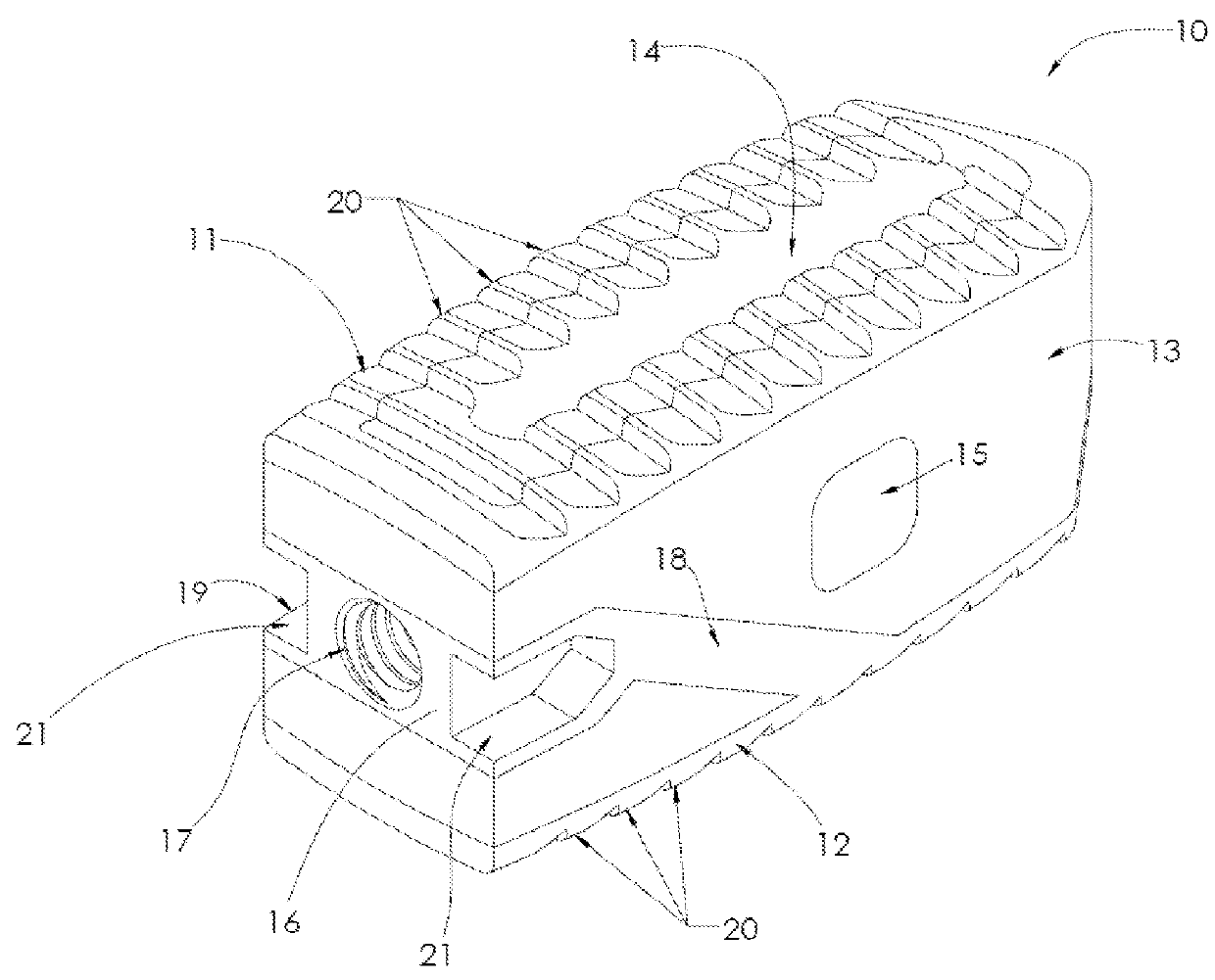
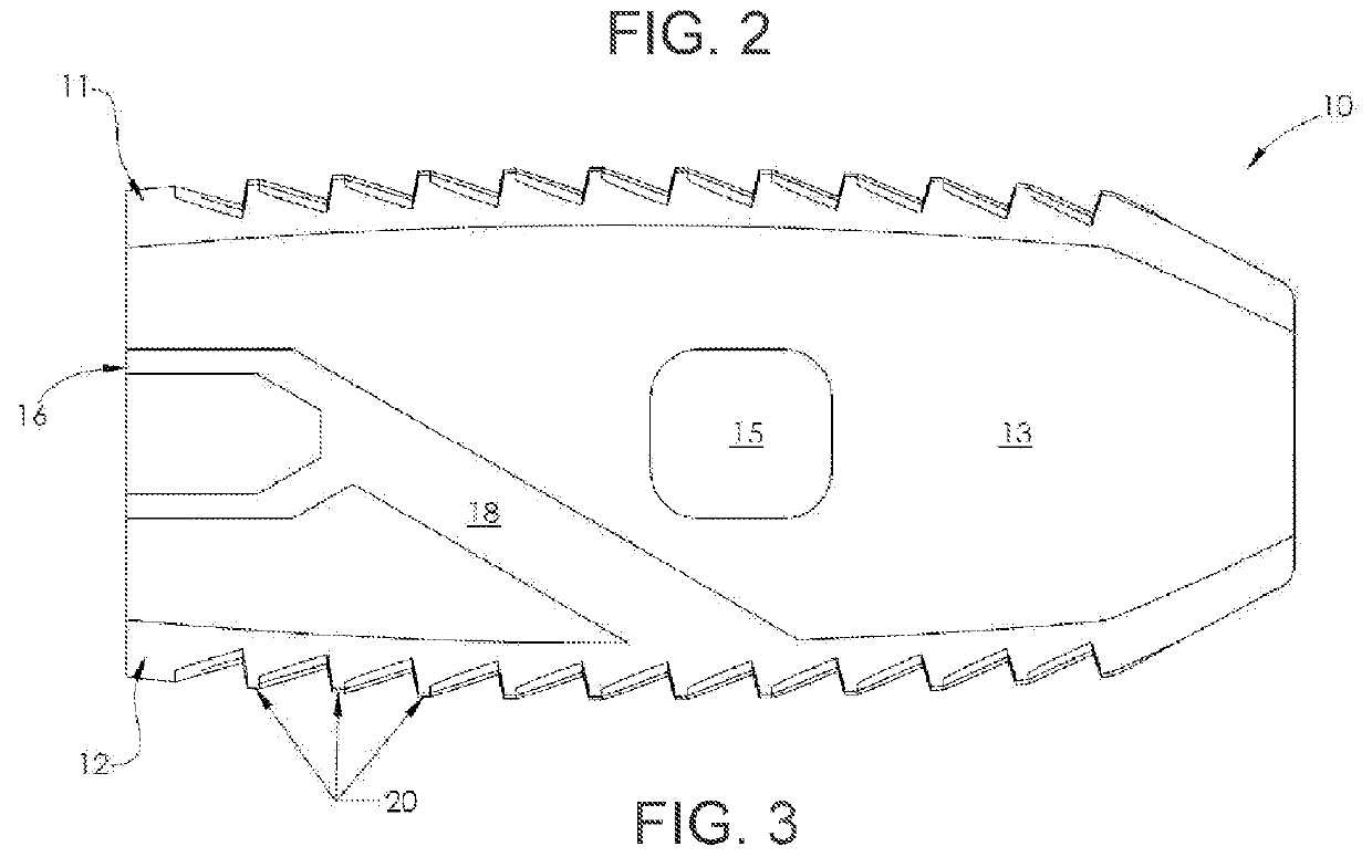
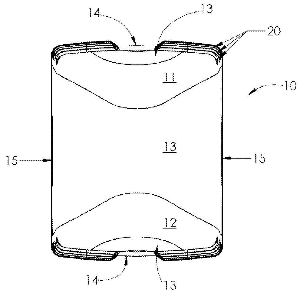
[0061]In many situations, it is desirable to use an implant that is capable of bone attachment or osteointegration over time. Examples of implants where attachment to bone or osteointegration is beneficial include, but are not limited to, cervical, lumbar, and thoracic interbody fusion implants, vertebral body replacements, osteotomy wedges, dental implants, bone stems, acetabular cups, cranio-facial plating, bone replacement and fracture plating. In many applications, it is also desirable to stress new bone growth to increase its strength. According to Wolff's law, bone will adapt to stresses placed on it so that bone under stress will grow stronger and bone that isn't stressed will become weaker.

[0062]In some aspects, the systems and methods described herein can be directed toward implants that are configured for osteointegration and stimulating adequately stressed new bone growth. The exemplary implants of the present invention are particularly useful for use in situations where ...


PUM


Abstract

In some aspects, the present invention is a medical implant with an independent endplate structure that can stimulate bone or tissue growth in or around the implant. When used as a scaffold for bone growth, the inventive structure can increase the strength of new bone growth. The independent endplate structures generally include implants with endplates positioned on opposite sides of the implant and capable of movement independent of one another. In most examples, the endplates have a higher elastic modulus than that of the bulk of the implant to allow the use of an implant with a low elastic modulus, without risk of damage from the patient's bone.A method of designing independent endplate implants is also disclosed, including ranges of elastic moduli for the endplates and bulk of the implant for given implant parameters. Implants with elastic moduli within the ranges disclosed herein can optimize the loading of new bone growth to provide increased bone strength.

Description

CROSS REFERENCE TO RELATED APPLICATIONS[0001]This application claims the benefit of U.S. Provisional Patent Application No. 62 / 346,720 filed Jun. 7, 2016, which is hereby incorporated by reference in its entirety.FIELD OF THE INVENTION[0002]The present invention relates to medical implants, in particular, to medical implants with independent endplates.BACKGROUND OF THE INVENTION[0003]Medical implants can be constructed using a wide range of materials, including metallic materials, Polyether ether ketone (hereinafter “PEEK”), ceramic materials and various other materials or composites thereof. There are competing priorities when selecting a material for an implant in order for the implant to pass regulatory testing. Some priorities when designing an implant could include strength, stiffness, fatigue resistance and radiolucency, and often some compromise is made during the design process.[0004]For example, to meet the strength requirements for an implant, the radiolucency may be less ...

Claims


Application Information

Patent Timeline
Patent Type & Authority Patents(United States)
IPC IPC(8): A61F2/44A61F2/30
CPCA61F2/4455A61F2/4425A61F2/442A61F2002/443A61F2002/30006A61F2002/30014A61F2002/30546A61F2/447A61F2/4465A61F2002/30593A61F2002/30904A61F2002/4495
Inventor JONES, CHRISTOPHER L.HELMAR, IANDIEHL, LUCASTINLEY, JASONCHAPPUIS, KEVIN D.
Owner NANOHIVE MEDICAL LLC
Why Eureka
Try Eureka