Method of mass separating ions and mass separator

a separation method and separator technology, applied in separation processes, mass spectrometers, stability-of-path spectrometers, etc., can solve the problems of increasing manufacturing costs, requiring more laboratory space to house instruments, and enlarged instruments. , to achieve the effect of reducing the effect of space charg

Active Publication Date: 2018-05-15
THERMO FISHER SCI BREMEN
View PDF21 Cites 14 Cited by
  • Summary
  • Abstract
  • Description
  • Claims
  • Application Information

AI Technical Summary

Benefits of technology

[0033]The analyser field may advantageously be set to the main analyser field (i.e. the analyser field in which the charged particles move along the main flight path) at all times, including the times at which ions are injected into the analyser and ejected from the analyser. In preferred embodiments the main flight path extends from and to the boundary of the analyser volume: from a point at which ions enter the analyser volume, to a point at which ions exit the analyser volume. Advantageously in these embodiments no additional ion optical devices are required within the analyser volume, nor are any power supplies connected to the analyser to be switched to effect entry and exit from the analyser. Furthermore, no significant distortion of the analyser field is induced by the entry and exit ports and consequently no field correction electrodes are required within the analyser to compensate. These advantages reduce the complexity of the analyser and its build cost. They also reduce the technical difficulties of analyser control during the processes of injecting ions into the analyser and ejecting ions from the analyser since no high speed switching of analyser power supplies is required.
[0122]All main flight paths are preferably also stable paths within the analyser. In the case where the second main flight path is stable, the beam may traverse the analyser once again on the second main flight path, thereby substantially increasing the total flight path and enabling in some embodiments at least doubling the flight path length through the analyser thereby increasing resolution of the TOF separation. One or more sets of electrodes are preferably also provided adjacent the second main flight path for constraining the arcuate divergence of the ions of interest on the second main flight path. One or more additional belt electrode assemblies or other means may be provided, e.g. to support additional arcuate lenses to focus the beam on the second main flight path. The additional belt electrode assemblies may support or be supported by belt electrode assemblies existing for the first main flight path, e.g. via a mechanical structure. Optionally, such additional belt electrode assemblies may be provided with field-defining elements protecting them from distorting the field at other points in the analyser. Such elements could be: resistive coatings, printed-circuit boards with resistive dividers and other means known in the art. Optionally, in addition to the second main flight path, the same principle may be applied to provide third or higher main flight paths if desired, e.g. by ejecting to the third main flight path from the second main flight path and so on. Each such main flight path preferably has one or more sets of electrodes adjacent each such main flight path for constraining the arcuate divergence of the ions of interest. Optionally, after traversing the second (or higher) main flight path, the beam may be ejected back to the first (or another) main flight path, e.g. to begin a closed path TOF.

Problems solved by technology

However, increases in a simple linear path length lead to an enlarged instrument size, increasing manufacturing cost and require more laboratory space to house the instrument.
However these prior art electrostatic traps in which ions orbit around inner electrodes and / or the analyser axis as so described have not been used to function as time of flight mass spectrometers as ions spread out around the inner electrode(s) with ions of the same mass to charge ratio forming rings.
Ejection of such rings to a detector cannot be accomplished easily without disrupting other rings of ions within the trap and means to sequentially eject ions of increasing or decreasing mass to charge ratio so as to produce a spectrum were not provided.
As described, these introduced obstacles on the path of the ions and the fringe field correction was not perfect, resulting in a reduction in sensitivity and resolution of the spectrometer.

Method used


Image

  • Method of mass separating ions and mass separator
  • Method of mass separating ions and mass separator
  • Method of mass separating ions and mass separator

Examples


Embodiment Construction

[0132]In order to more fully understand the invention, various embodiments of the invention will now be described by way of examples only and with reference to the Figures. The embodiments described are not limiting on the scope of the invention.

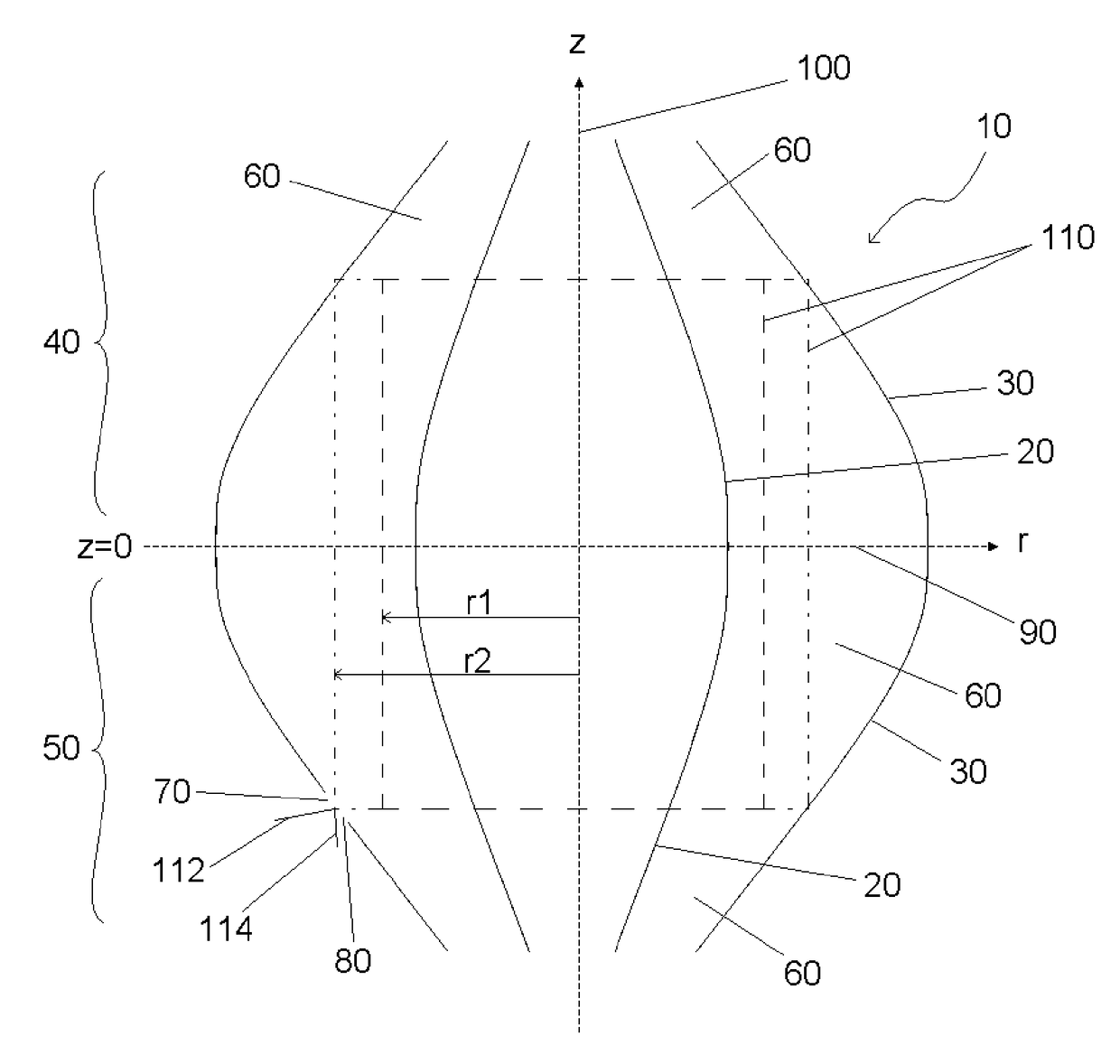
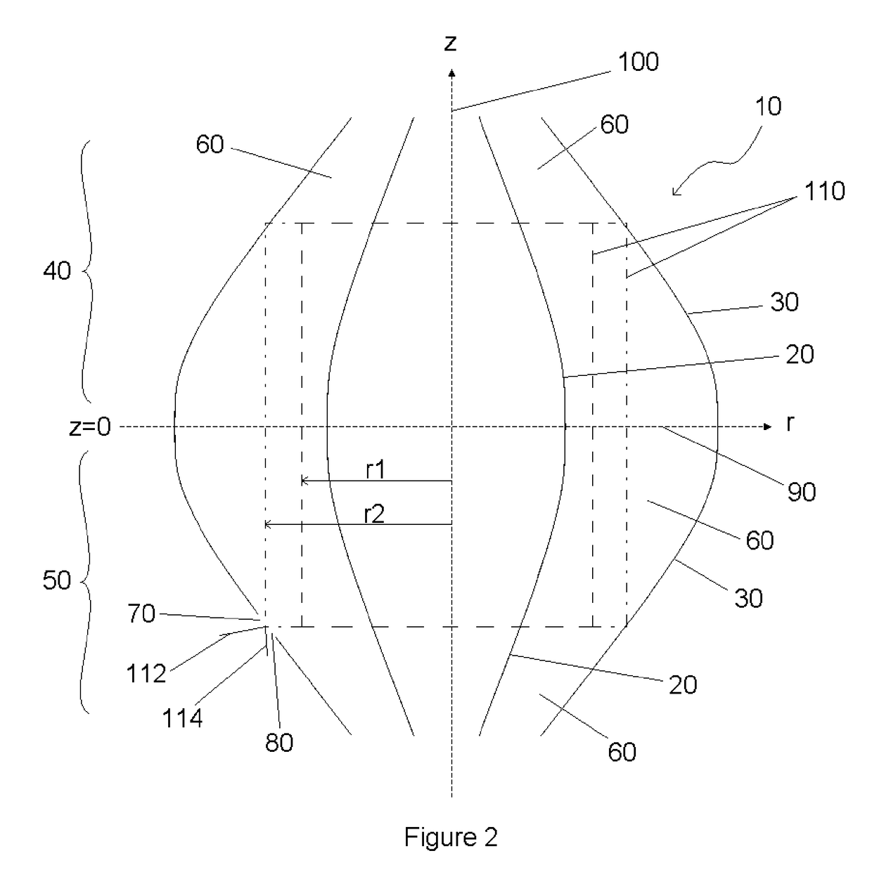
[0133]One preferred embodiment of the present invention utilises the quadro-logarithmic potential distribution described by equation (1) as the main analyser field. FIG. 2 is a schematic cross sectional side view of the electrode structures for such a preferred embodiment. Analyser 10 comprises inner and outer field-defining electrode systems, 20, 30 respectively, of two opposing mirrors 40, 50. The inner and outer field-defining electrode systems in this embodiment are constructed of gold-coated glass. However, various materials may be used to construct these electrode systems: e.g. Invar; glass (zerodur, borosilicate etc) coated with metal; molybdenum; stainless steel and the like. The inner field-defining electrode system 20 is of spindle...


PUM


Abstract

A method of separating ions according to their time of flight is provided comprising: a. providing an analyzer comprising two opposing ion mirrors, each mirror comprising inner and outer field-defining electrode systems elongated along an analyzer axis with the outer field-defining electrode system surrounding the inner field-defining electrode system and creating therebetween an analyzer volume; b. injecting ions into the analyzer volume or creating ions within the analyzer volume so that they separate according to their time of flight as they travel along a main flight path while undergoing a plurality of axial oscillations in the direction of the analyzer axis and a plurality of radial oscillations while orbiting about one or more inner field-defining electrodes; c. the plurality of axial oscillations and plurality of radial oscillations causing the separated ions to intercept an exit port after a predetermined number of orbits. Also provided is an analyzer for performing the method, comprising: the two opposing ion mirrors which abut at a first plane, wherein the outer field-defining electrode system of one mirror comprises two sections, the sections abutting at a second plane, comprising a first section between the first plane and the second plane, and a second section adjacent the first section and wherein the first section has at least a portion which extends radially from the analyzer axis a greater extent than an adjacent portion of the second section at the second plane.

Description

FIELD OF THE INVENTION[0001]This invention relates to the field of mass separating ions, and in particular to methods and apparatus for the separating of ions using time-of-flight (TOF) multi-reflection (MR) mass analysers.BACKGROUND[0002]Time-of-flight mass spectrometers are widely used to determine the mass to charge ratio of charged particles on the basis of their flight time along a path. The charged particles, usually ions, are emitted from a pulsed source in the form of a packet, and are directed along a prescribed flight path through an evacuated space to impinge upon or pass through a detector. (Herein ions will be used as an example of charged particles.) In its simplest form, the path follows a straight line and in this case ions leaving the source with a constant kinetic energy reach the detector after a time which depends upon their mass to charge ratio, more massive ions being slower. The difference in flight times between ions of different mass-to-charge ratio depends ...

Claims


Application Information

Patent Timeline
Patent Type & Authority Patents(United States)
IPC IPC(8): H01J49/00H01J49/42H01J49/40
CPCH01J49/40H01J49/4245H01J49/406H01J49/405H01J49/427
Inventor MAKAROV, ALEXANDER A.
Owner THERMO FISHER SCI BREMEN
Why Eureka
Try Eureka