Surgical device for controlled anchoring in the intestine

a surgical device and intestine technology, applied in non-surgical orthopedic devices, blood vessels, obesity treatment, etc., can solve the problems of short post-operative ileus period, unusually long contrary, and separation of temporary or permanent anchor elements from the intestine wall,

Active Publication Date: 2018-05-29
KHOSROVANINEJAD CHARAM
View PDF121 Cites 3 Cited by
  • Summary
  • Abstract
  • Description
  • Claims
  • Application Information

AI Technical Summary

Benefits of technology

[0022]The object of the present invention is to provide a device that makes it possible to control and to modify at will the behavior of the anchor element in the intestine.
[0023]More particularly, the object of the present invention is to provide a novel type of surgical device that makes it possible at will to modify the duration of the period it remains static, i.e. the time that elapses between the device being put into place in the intestine and beginning to migrate, and / or the time the device remains dynamically in the intestine, i.e. the time that elapses between the beginning of the migration of the device and its elimination from the intestine.
[0024]Still more particularly, the object of the present invention is to provide a device for which migration can be slowed down and / or interrupted in the event of anastomotic fistulas appearing so as to allow said fistula to heal before said device migrates to the level of said fistula.

Problems solved by technology

In all of the applications mentioned above, it can happen that said temporary or permanent anchor elements separate from the wall of the intestine and migrate too soon.
Nevertheless, it can happen that the post-operative ileus period is exceptionally short or on the contrary exceptionally long, with periods lying in the range 24 hours to four weeks, such that either the device migrates through the anastomosis before it has had time to heal, or on the contrary the device remains anchored in the intestine for too long.
The major drawback of that device consists in the risk of the stent migrating at an unwanted moment, and thus the risk of the entire device migrating into the intestine with at best the need to extract the device by endoscopic maneuvers, and at worse the risk of the intestine becoming occluded or perforated and making further surgery necessary.
Furthermore, the device described in the prior art for temporary anchorage and for protecting an anastomosis cannot prevent anastomotic fistulas arising, which fistulas take considerably longer to heal than the time the device remains in the intestine, in other words the temporary protection device runs the risk of being eliminated long before healing of a fistula, if there is one.
Under such circumstances, the practitioner needs to make a protective stomy, which greatly decreases the therapeutic advantage of the device.
Unfortunately, the coefficient of friction of the inner walls of the intestine is very low because of the presence of water, thus having the consequence of making it easier for the stent to slide.
Nevertheless, that does not make it possible to exert direct control at will in variable amounts on the device in order to modify its behavior.
However, apart from the risk of causing traumatic lesions in the walls of the intestine, that method likewise provides no direct control over the behavior of the stent.
However, once more, the resorption process is not governed by any external action on the intestine, so it does not make it possible to exercise any direct control at will and in varying amounts on the device in order to modify its anchoring properties.

Method used


Image

  • Surgical device for controlled anchoring in the intestine
  • Surgical device for controlled anchoring in the intestine
  • Surgical device for controlled anchoring in the intestine

Examples


Embodiment Construction

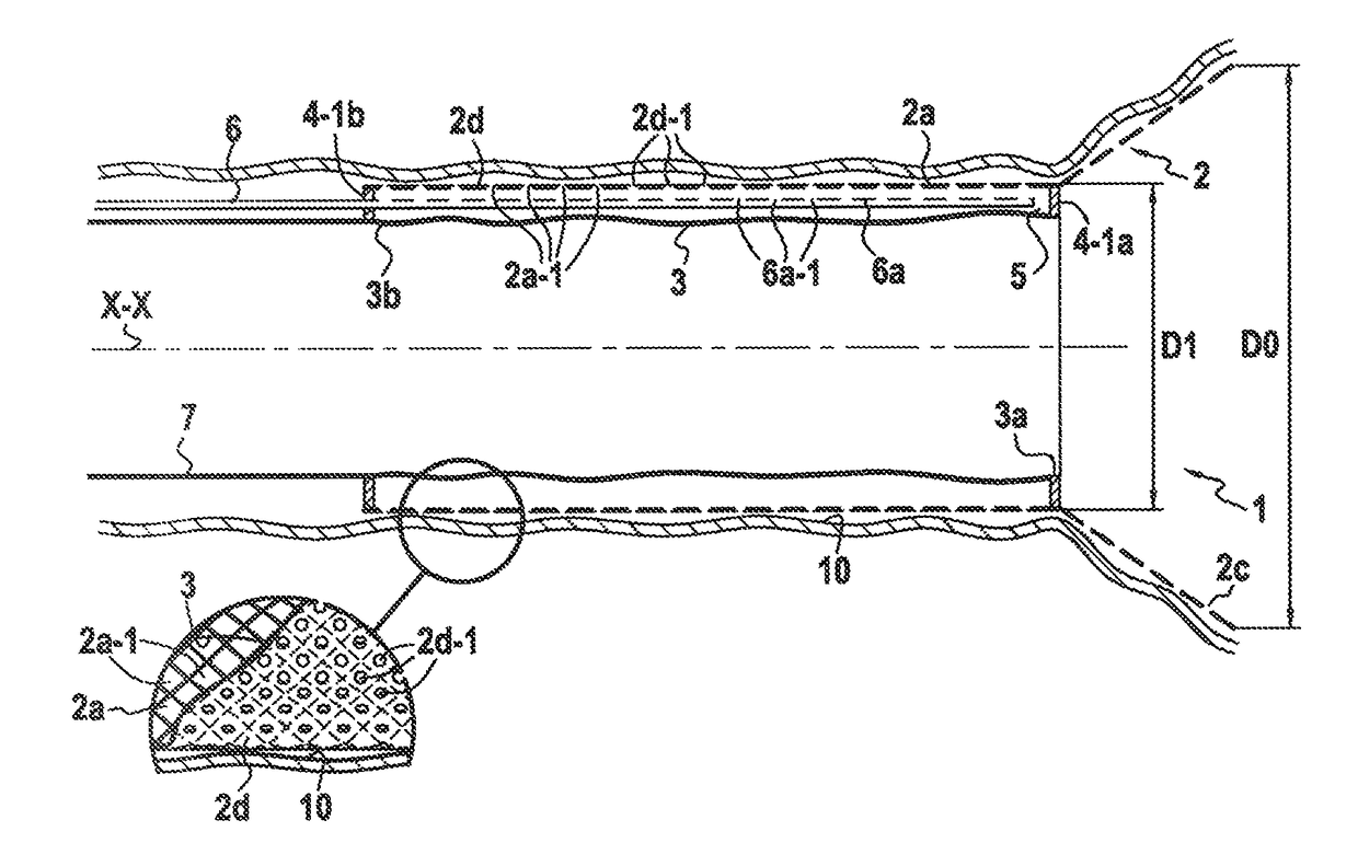
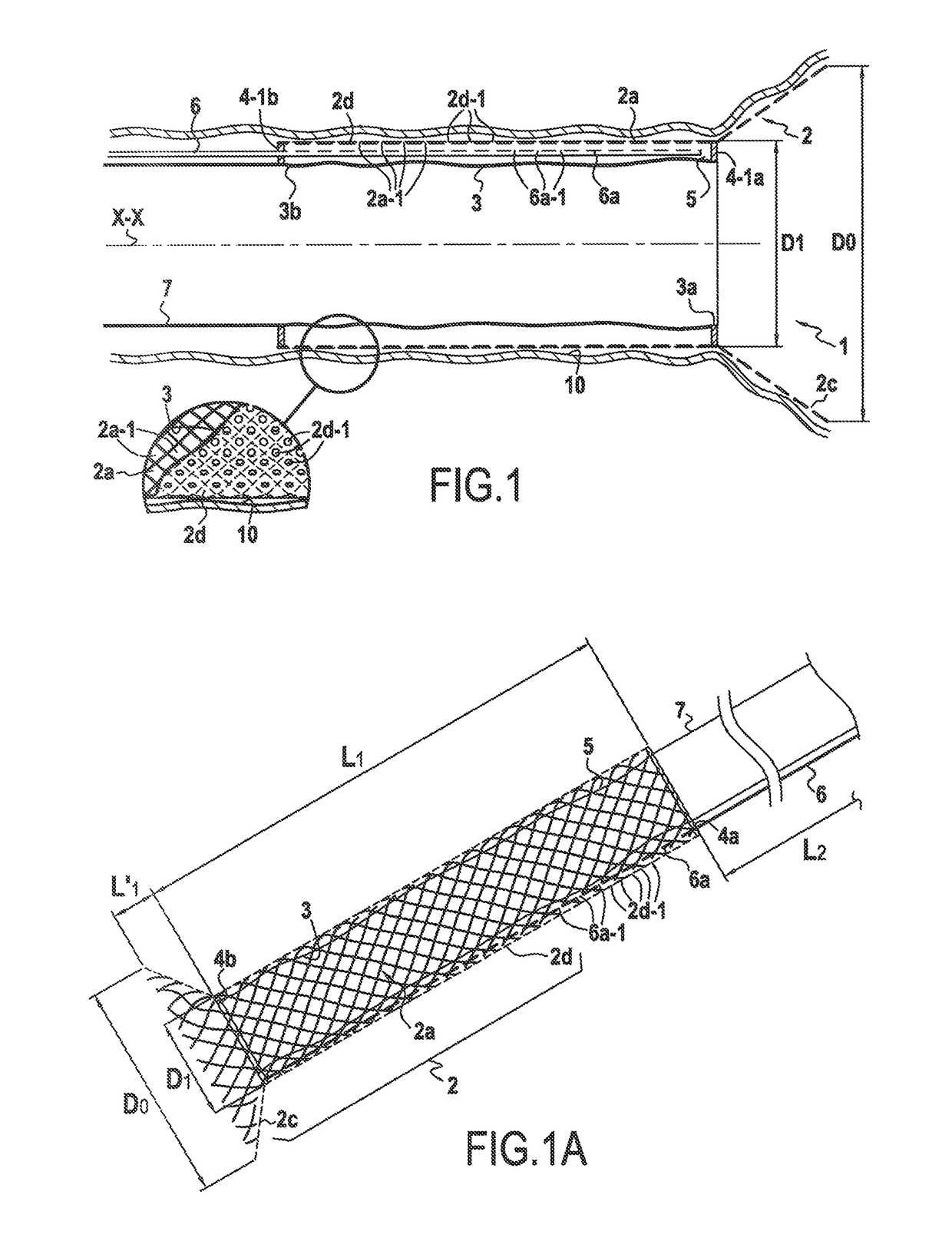
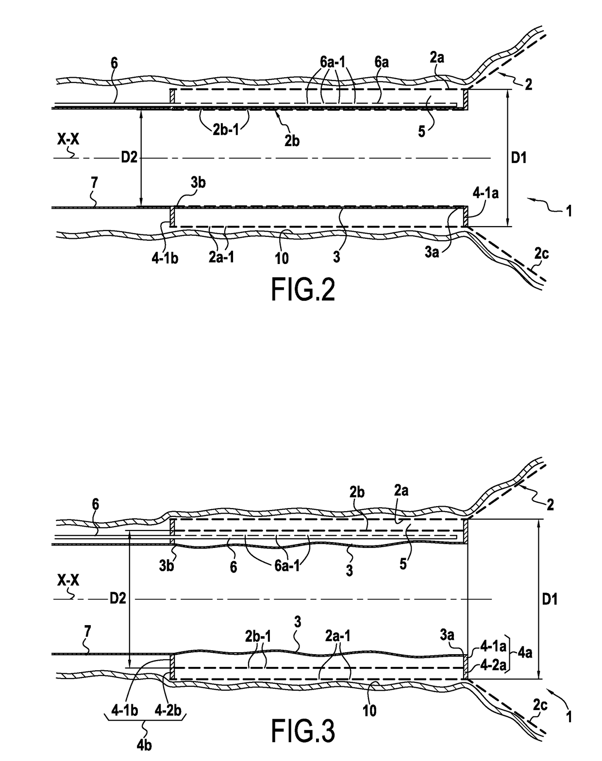
[0170]FIG. 1 shows a surgical device 1 for anchoring on the mucous membrane of the inner wall of the intestine 10, the device comprising a temporary anchor element 2 constituted by a first and only semi-rigid hollow longitudinal element defining a wall in the form of a surface of revolution around a longitudinal axis XX having a substantially cylindrical multiply-perforated main portion of substantially circular section referred to as a “first” wall 2a, said anchor element 2 being made of a material that gives it properties of radial elasticity so as to enable it to be compressed radially into a retracted position and to adopt a said maximum radially expanded position after the radial compression has been released, whereby said multiply-perforated wall presents a first outer diameter that can be varied in controlled manner between:[0171]a minimum first outer diameter D1′ in said radially retracted position of said first wall, which is preferably no more than 10 mm; and[0172]a maximu...


PUM


Abstract

The present invention relates to a surgical anchor device (1) suitable for being anchored on the mucous membrane of the inner wall of the intestine (10), the device comprising a temporary anchor element (2) presenting anchoring that can be modified in controlled manner and comprising a first substantially cylindrical multiply-perforated wall presenting properties of radial elasticity whereby said first wall presents an outer diameter that can be varied in controlled manner, the device being characterized in that at least a portion of the inner surface of said first wall (2a) is lined with an independent leakproof inner sheath having only its longitudinal ends (3a, 3b) fastened to said anchor element (2) in such a manner as to define a suction chamber (5) between said inner sheath (3) and said first wall, said temporary anchor element (2) being coupled to a flexible or semi-rigid tube referred to as an “injection-suction” tube (6), extending outside said anchor element (2), an open end (6a) of said injection-suction tube opening out into said suction chamber (5) enabling air to be injected into or sucked out from said suction chamber.

Description

[0001]This application is a 371 of PCT / FR2012 / 051576, filed on Jul. 5, 2012, which claims priority to French Application No. 1156771, filed Jul. 25, 2011.BACKGROUND OF THE INVENTION[0002]The present invention relates to a surgical device for anchoring to the mucous membrane of the inner wall of the intestine, the device comprising an anchor element having at least one first semi-rigid hollow longitudinal element defining a wall forming a surface of revolution about a longitudinal axis with a substantially cylindrical multiply-perforated main portion of substantially circular section referred to as the “first” wall, said anchor element being made of a material giving it radial elasticity properties such that it can be compressed radially into a retracted position and can adopt a said maximally radially expanded position after the radial compression has been released, whereby said first multiply-perforated wall presents a diameter that can be varied in controlled manner.[0003]More par...

Claims


Application Information

Patent Timeline
Patent Type & Authority Patents(United States)
IPC IPC(8): A61B17/08A61F5/00A61F2/04A61F2/07A61F2/95A61F2/06
CPCA61B17/08A61F2/04A61F5/0013A61F5/0076F04C2270/041A61F2/95A61F2002/044A61F2002/075A61F2/064A61F2002/045A61B2017/00818A61B2017/00995A61B2017/00862A61F2002/9528A61B2017/308A61B2090/0815A61F5/0089A61B17/1114
Inventor KHOSROVANINEJAD, CHARAM
Owner KHOSROVANINEJAD CHARAM
Why Eureka
Try Eureka