Control device for internal combustion engine

a control device and internal combustion engine technology, applied in the direction of engine starters, electrical control, exhaust treatment electric control, etc., can solve the problems of not being able to suitably control the air-fuel ratio of the exhaust gas, not being able to accurately, and a certain extent of time taken for the sensor heater, etc., to achieve the effect of small consumption of electric power by the sensor heater

Inactive Publication Date: 2018-05-29
TOYOTA JIDOSHA KK
View PDF10 Cites 4 Cited by
  • Summary
  • Abstract
  • Description
  • Claims
  • Application Information

AI Technical Summary

Benefits of technology

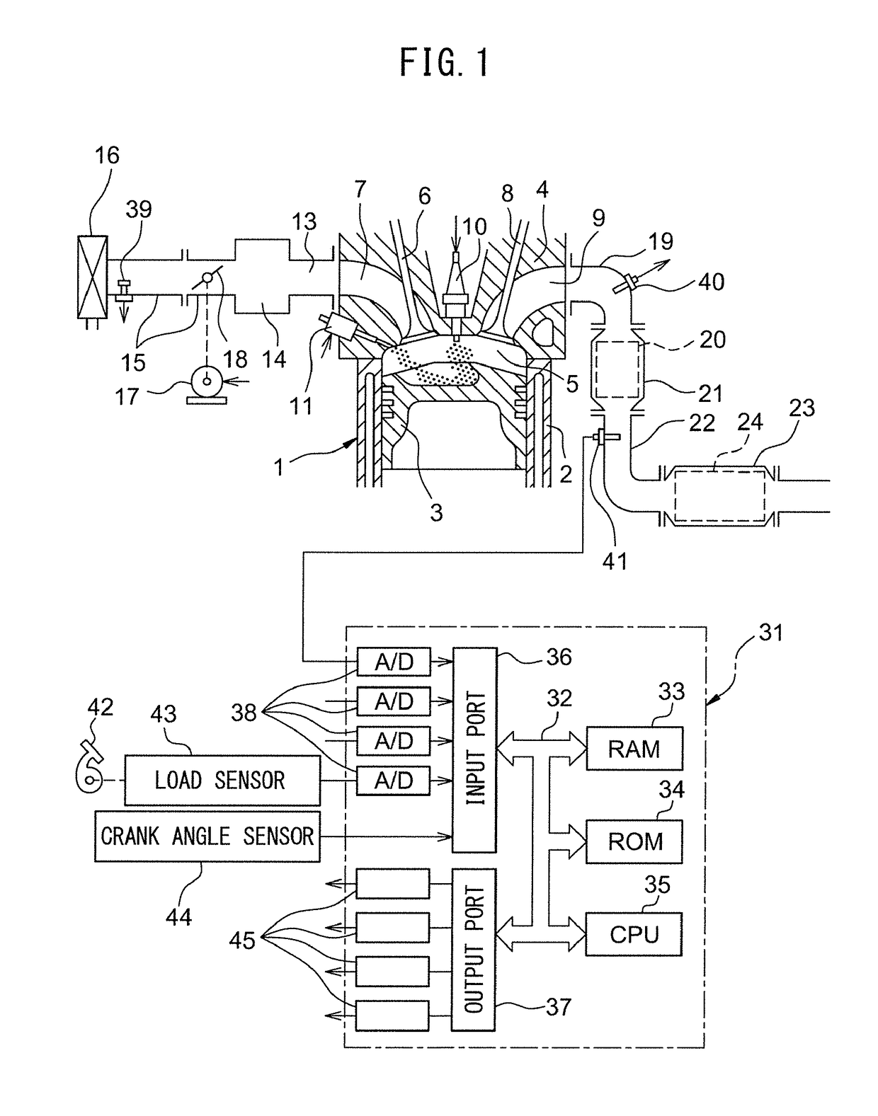
[0007]Therefore, in view of the above problem, an object of the present disclosure is to provide a control device of an internal combustion engine keeping consumption of electricity by the sensor heaters small while being able to suitably control the air-fuel ratio of the exhaust gas right after engine restart.
[0021]the electronic control unit is further configured to control the downstream side sensor heater so that the temperature of the downstream air-fuel ratio sensor becomes lower while the internal combustion engine is stopped by the automatic stop function compared with during engine operation.
[0025]the electronic control unit is further configured to set the target air-fuel ratio so that the average value of the rich degree of the target air-fuel ratio while the target air-fuel ratio is set to the rich air-fuel ratio and the average value of the lean degree of the target air-fuel ratio while the target air-fuel ratio is set to the lean air-fuel ratio become larger when performing double feedback control compared to when performing single feedback control.
[0039]the electronic control unit is further configured to: control the target air-fuel ratio based on a difference between the output air-fuel ratio of the downstream air-fuel ratio sensor and the stoichiometric air-fuel ratio by PID control so that the difference becomes smaller both in feedback control and in single feedback control; and make at least one of the gains of the proportional gain, integral gain, and differential gain in the PID control smaller when performing single feedback control compared to when performing double feedback control.
[0041]the electronic control unit is further configured to: control the target air-fuel ratio based on a difference between the output air-fuel ratio of the downstream air-fuel ratio sensor and the stoichiometric air-fuel ratio by PI control so that the difference becomes smaller both in double feedback control and in single feedback control; and make at least one of the gains of the proportional gain and integral gain in the PI control smaller when performing single feedback control compared to when performing double feedback control.
[0042]According to embodiments of the present disclosure, there is provided a control device for an internal combustion engine keeping consumption of electric power by the sensor heaters small while being able to suitably control the air-fuel ratio of the exhaust gas right after engine restart.

Problems solved by technology

However, when the temperature of an air-fuel ratio sensor is less than an activation temperature, a certain extent of time is taken for a sensor heater to raise the air-fuel ratio sensor to the activation temperature or more.
For this reason, it is not possible to accurately detect the air-fuel ratio of the exhaust gas at the two air-fuel ratio sensors of the upstream air-fuel ratio sensor and downstream air-fuel ratio sensor for a certain extent of time after restart of the internal combustion engine and according it is no longer possible to suitably control the air-fuel ratio of the exhaust gas.
However, to constantly maintain the temperatures of these two air-fuel ratio sensors at the activation temperature or more while the internal combustion engine is stopped by the automatic stop function, the sensor heaters require large electric power.
In the end, this leads to deterioration of the fuel economy of the internal combustion engine.

Method used


Image

  • Control device for internal combustion engine
  • Control device for internal combustion engine
  • Control device for internal combustion engine

Examples


second embodiment

[0190]Next, referring to FIG. 13 to FIG. 15, a control device of a second embodiment of the present disclosure will be explained. The configuration and control of the control device of the second embodiment are basically similar to the control and configuration of the control device of the first embodiment except for the points explained below.

[0191]In the double breakdown control of the first embodiment, the target air-fuel ratio is maintained at a certain lean set air-fuel ratio during the lean time period while the target air-fuel ratio is maintained at a certain rich set air-fuel ratio during the rich time period. As opposed to this, in the double breakdown control of the present embodiment, the target air-fuel ratio is maintained at the lean air-fuel ratio during the lean time period while the lean degree of the target air-fuel ratio is lowered during the lean time period. In addition, the target air-fuel ratio is maintained at the rich air-fuel ratio during the rich time perio...

third embodiment

[0220]Next, referring to FIG. 17, a control device of a third embodiment of the present disclosure will be explained. The configuration and control of the control device of the third embodiment are basically similar to the controls and configurations of the control devices of the first embodiment and second embodiment except for the points explained below.

[0221]In the first embodiment, during both double FB control and single FB control, fixed double breakdown control is performed. On the other hand, in the second embodiment, during both double FB control and single FB control, fluctuating double breakdown control is performed. As opposed to this, in the present embodiment, during double FB control, fluctuating double breakdown control is performed, while during single FB control, fixed double breakdown control is performed.

[0222]FIG. 17 is a time chart of the air-fuel ratio correction amount AFC etc. around the time t2 of FIG. 6 in the present embodiment. In the example shown in FI...

fourth embodiment

[0228]Next, referring to FIG. 18 to FIG. 21, a control device of a fourth embodiment of the present disclosure will be explained. The configuration and control of the control device of the fourth embodiment are basically similar to the configurations and control of the first embodiment to third embodiment except for the points explained below.

[0229]

[0230]In the double FB control of the present embodiment, feedback control is performed based the output air-fuel ratio of the upstream air-fuel ratio sensor 40 and the target air-fuel ratio is set by rich breakdown control. Below, rich breakdown control will be explained.

[0231]In rich breakdown control, the target air-fuel ratio is set based on the output air-fuel ratio of the downstream air-fuel ratio sensor 41 etc. Specifically, when the output air-fuel ratio of the downstream air-fuel ratio sensor 41 becomes the rich air-fuel ratio, the target air-fuel ratio is set to the lean set air-fuel ratio. In addition, in rich breakdown control...


PUM


Abstract

A control device for an internal combustion engine comprises an air-fuel ratio control part configured to control the air-fuel ratio of the exhaust gas and a heating control part configured to control the heating of the air-fuel ratio sensors. The heating control part controls the sensor heaters so that the temperature of the upstream air-fuel ratio sensor becomes less than the activation temperature and so that the temperature of the downstream air-fuel ratio sensor becomes the activation temperature or more while the internal combustion engine is stopped by the automatic stop function. The air-fuel ratio control part controls the exhaust air-fuel ratio based on the outputs of the two air-fuel ratio sensors during engine operation and control the air-fuel ratio temporarily based on only the output of the downstream air-fuel ratio sensor after the internal combustion engine has been restarted after automatic stop.

Description

CROSS-REFERENCE TO RELATED APPLICATIONS[0001]The present application claims priority to Japanese Patent Application No. 2015-134607 filed Jul. 3, 2015, the entire contents of which are hereby incorporated herein by referenceTECHNICAL FIELD[0002]The present disclosure relates to a control device for an internal combustion engine.BACKGROUND ART[0003]Japanese Patent Publication No. 2010-185386A discloses a control device used in an automatically stoppable internal combustion engine provided with an exhaust purification catalyst provided in an exhaust passage of the internal combustion engine, an upstream air-fuel ratio sensor provided in the exhaust passage at an upstream side of the exhaust purification catalyst in the direction of flow of exhaust, a downstream air-fuel ratio sensor provided in the exhaust passage at a downstream side of the exhaust purification catalyst in the direction of flow of exhaust, an upstream side sensor heater heating the upstream air-fuel ratio sensor, and...

Claims


Application Information

Patent Timeline
Patent Type & Authority Patents(United States)
IPC IPC(8): F02D41/00F02D41/14F02D41/06F01N3/10F02D41/26F02D35/00F01N11/00F02D41/02F01N9/00
CPCF02D41/1494F02D35/0015F02D41/065F02D41/1441F02D41/1454F02D41/26F01N3/101Y02T10/22F01N9/00F01N11/007F01N2430/06F01N2560/025F01N2560/14F01N2560/20F01N2900/08F02D41/0295F02D2041/1418F02D2200/0814F02N11/0829Y02T10/12Y02T10/40
Inventor HAYASHITA, GOIDE, KOJI
Owner TOYOTA JIDOSHA KK
Why Eureka
Try Eureka