
Enclosure temperature control system

a temperature control system and enclosure technology, applied in heating types, renewable energy machines, greenhouse gas reduction, etc., can solve the problem that solar panels cannot produce power, and achieve the effect of reducing or no net electrical power

Active Publication Date: 2018-06-19
THE BOSE FAMILY TRUST
View PDF24 Cites 0 Cited by
  • Summary
  • Abstract
  • Description
  • Claims
  • Application Information

AI Technical Summary

Benefits of technology

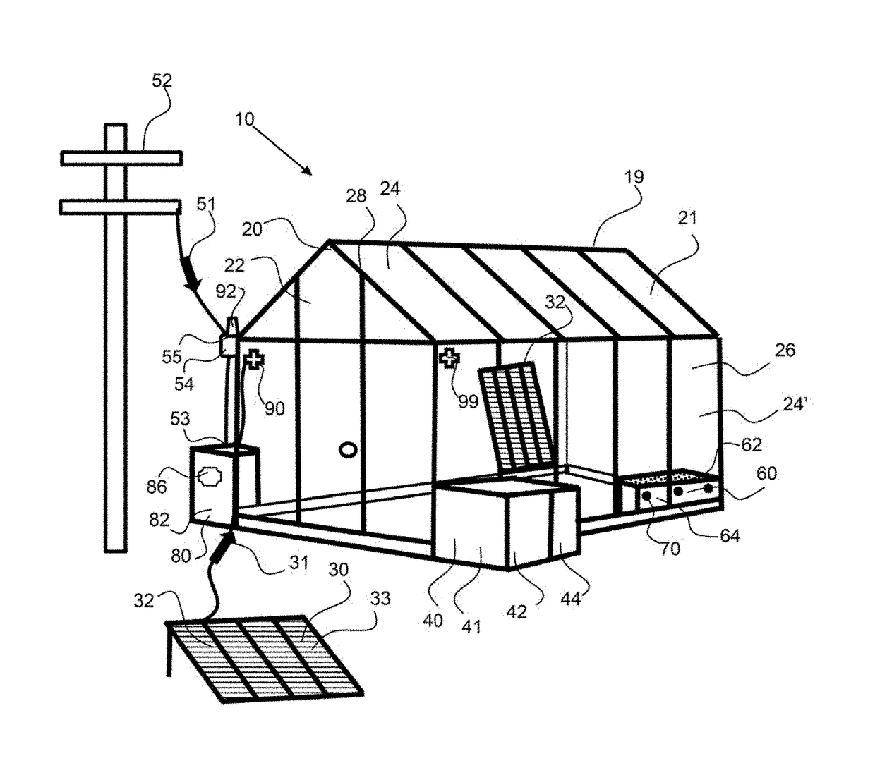
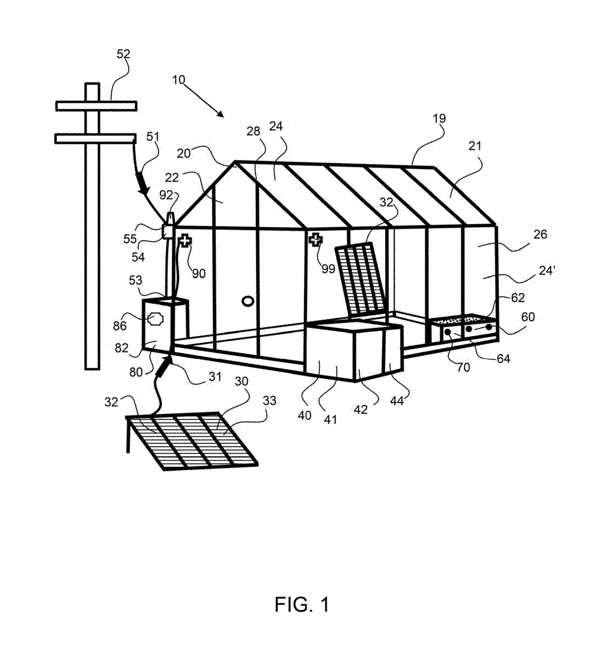
[0005]The invention is directed to a temperature control system for enclosures, and particularly greenhouses that employ renewable power sources as well as phase change materials. Greenhouses required temperature control within a certain range to ensure that the plants therein grow and are not stressed due to temperature extremes or fluctuations. Other enclosures that may benefit from a temperature control system as described herein include enclosures that have a high heat source therein, such as data centers, computer server enclosures, as well as dwellings, homes, office areas, recreational vehicles, RV's, and the like. An exemplary temperature control system of the present invention may enable temperature control with reduced or no net electrical power required from a grid power source.
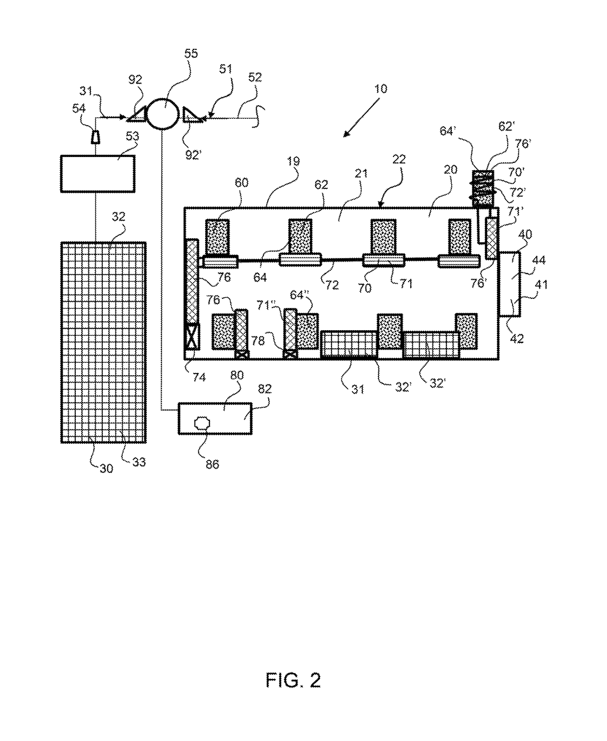
[0018]An exemplary heat sink may comprise one or more tanks for storing the phase change material. The phase change material may perform better in relatively small containers; therefore, a plurality of discrete tanks may be preferred. An individual tank may have a volume of about 2 liters or more, about 4 liters or more, about 10 liters or more, about 20 liters or more, no more than about 30 liters, no more than about 20 liters, no more than about 10 liters and any range between and including the volumes provided. Theses tanks may be configured within the interior of the greenhouse or outside of the greenhouse. For example, a plurality of tanks may be configured and dispersed within the greenhouse, contain a phase change material with a melting temperature between the lower and upper threshold temperature limits of the greenhouse, to more effectively absorb heat and release heat throughout the greenhouse. When a tank is configured outside of the greenhouse, a heat transfer system comprising a conduit may extend from the interior of the greenhouse to the tank thereby providing heat transfer from the phase change material to the interior of the greenhouse by way of the heat transfer fluid. A heat transfer fluid may flow through a radiator configured within the greenhouse to more effectively and quickly transfer heat from the heat transfer fluid to the interior of the greenhouse.
[0019]An exemplary phase change material is a composite phase change material comprising a solid conductor component that is configured within the phase change material to conduct heat to and from the phase change material. An exemplary solid conductor component is a porous or permeable metal, such as a metal screen, mesh, or fabric. The solid conductor component may be coupled with the tank and configured to conduct heat from the phase change material to the tank. The tank may be couple with a heat transfer device or a heat transfer system to more effectively conduct heat to and from the phase change material. For example, a tank may comprise a plurality of fins that extend from the exterior of the tank and these fins may be subject to airflow from an airflow device, or to natural convection to more effectively exchange heat with the tank and with the phase change material therein. A heat transfer system may comprise a conduit that is configured in contact with the tank, such as being wrapped around the tank, wherein a heat transfer fluid passes through the conduit to carry heat to and / or from the tank and phase change material. In an exemplary embodiment, a solid conductor component is a conduit that is coupled with heat transfer conduit, whereby the heat transfer fluid flows through the tank. A solid conductor conduit may spiral or run in a serpentine configuration within a tank to provide more surface area of contact between said conduit and the phase change material. A tank may comprise a transparent window to allow sunlight to pass into the tank to heat the phase change material within the tank thereby reducing and / or eliminating the need for a heat transfer system to melt the phase change material.

Problems solved by technology

During the night however, the solar panels will not be producing power and this is when heat from the phase change material may be used to heat the interior of the greenhouse.

Method used


Image

  • Enclosure temperature control system
  • Enclosure temperature control system
  • Enclosure temperature control system

Examples


Embodiment Construction

[0033]Corresponding reference characters indicate corresponding parts throughout the several views of the figures. The figures represent an illustration of some of the embodiments of the present invention and are not to be construed as limiting the scope of the invention in any manner. Further, the figures are not necessarily to scale, some features may be exaggerated to show details of particular components. Therefore, specific structural and functional details disclosed herein are not to be interpreted as limiting, but merely as a representative basis for teaching one skilled in the art to variously employ the present invention.

[0034]As used herein, the terms “comprises,”“comprising,”“includes,”“including,”“has,”“having” or any other variation thereof, are intended to cover a non-exclusive inclusion. For example, a process, method, article, or apparatus that comprises a list of elements is not necessarily limited to only those elements but may include other elements not expressly ...


PUM


Abstract

An enclosure temperature control system utilizes a renewable power source and a thermal sink to reduce the overall power requirements from a power grid. A renewable power source, such as a solar panel may provide power that drives the components required to maintain the greenhouse temperature within upper and lower limits, including a HVAC system and / or a heat transfer system coupled with a thermal sink. The thermal sink includes a phase change material that releases heat when it solidifies and this heat can be used to heat the greenhouse. Likewise, the phase change material absorbs heat during the day to reduce the temperature within the greenhouse. A heat transfer system may be coupled with the phase change material and a solid conductor component within the tank of a phase change material may increase thermal transfer rate.

Description

CROSS REFERENCE TO RELATED APPLICATIONS[0001]This application claims the benefit of priority to U.S. provisional patent application No. 62 / 194,022, filed on Jul. 17, 2015 and entitled Near Zero Carbon Emission Greenhouse Technology; the entirety of which is hereby incorporated by reference herein.BACKGROUND OF THE INVENTIONField of the Invention[0002]The present invention relates to hybrid heating systems that employ renewable energy technologies, such as photovoltaic panels or cells, for regulating the temperature within an enclosure and particularly greenhouse.Background[0003]Many factors are contributing to the increase in greenhouses and Controlled Environment Agriculture (CEA) enclosures, including, increasing population, loss of farmlands to housing and other uses, global climate change and increasing demand for organic products. Greenhouses are an enclosure that allows sunlight to pass through the enclosure wells to grow plants, whereas CEA enclosures utilizes powered light s...

Claims


Application Information

Patent Timeline
Patent Type & Authority Patents(United States)
IPC IPC(8): A01G9/24F24F5/00
CPCA01G9/243A01G9/246F24F5/0021F24F5/0046F24F5/0071Y02E70/30Y02A30/272Y02B10/20Y02B10/24Y02E60/147F24F2005/0067Y02E60/14Y02P60/12Y02A40/25
Inventor BOSE, ASHOKE
Owner THE BOSE FAMILY TRUST
Learn More