Frequency-scan traveling wave antenna

a traveling wave and antenna technology, applied in the direction of antennas, non-resonant long antennas, electric long antennas, etc., can solve the problems of interference with the use of such antennas, burdening the antenna, adversely affecting the quality of the performance, etc., and achieve high performance

Inactive Publication Date: 2002-06-04
UNITED STATES OF AMERICA
View PDF4 Cites 8 Cited by
  • Summary
  • Abstract
  • Description
  • Claims
  • Application Information

AI Technical Summary

Benefits of technology

The present invention generally relates to a frequency-scan traveling wave antenna, and more particularly, to a frequency-scan traveling wave antenna which operates at millimeter wave frequencies. In particular, the present invention provides a high performance traveling wave antenna which scans by frequency, and which can be used effectively as a component of collision avoidance radar systems and imaging radar systems.

Problems solved by technology

However, such frequency-scan traveling wave antennas are burdened by disadvantages, and those disadvantages adversely affect the quality of their performance.
This interferes with the use of such antennas as an effective component of collision avoidance radar systems and imaging radar systems.
Problems with traveling wave antennas of the prior art include the following: inferior radiating element design, inadequate impedance match, insufficient power weighting accuracy, and inferior phase coherence across an array.

Method used


Image

  • Frequency-scan traveling wave antenna
  • Frequency-scan traveling wave antenna
  • Frequency-scan traveling wave antenna

Examples


Embodiment Construction

The invention will now be described in more detail with reference to the various figures of the drawings.

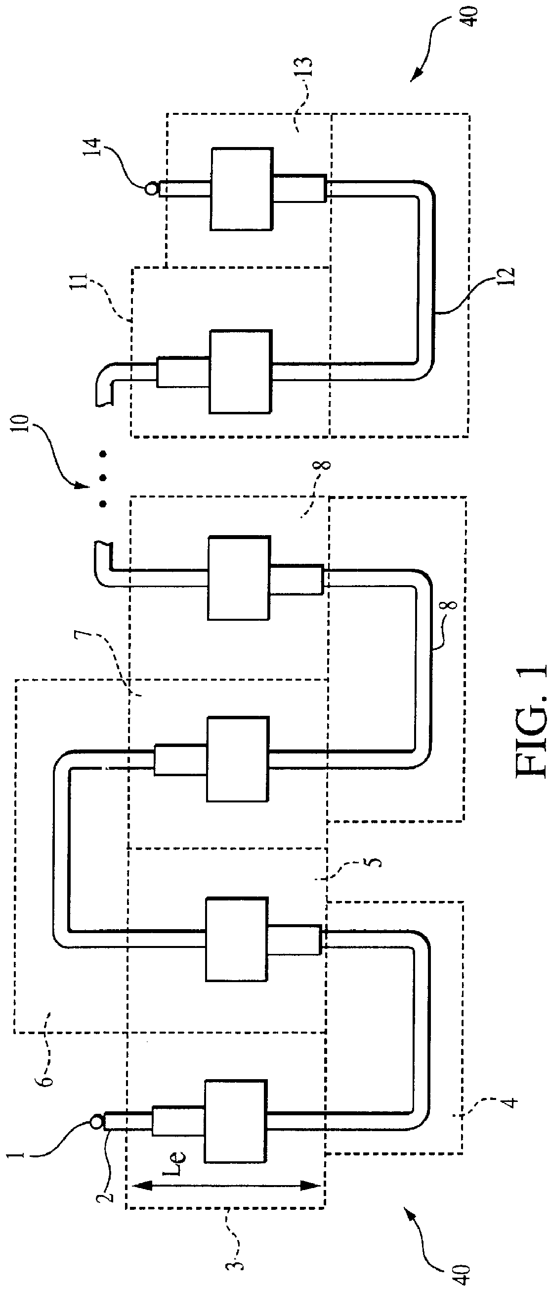
FIG. 1 is a diagrammatic representation of a preferred traveling wave antenna array employed in the present invention. As seen therein, the frequency-scan traveling wave antenna 40 of the present invention comprises the following elements: input port 1; quarter wave transformer 2; first radiator element 3; first delay line 4; second radiator element 5; second delay line 6; third radiator element 7; third delay line 8; fourth radiator element 9; intervening delay lines and radiator elements generally indicated by reference numeral 10; penultimate radiator element 11; final delay line 12; final radiator element 13; and output port 14.

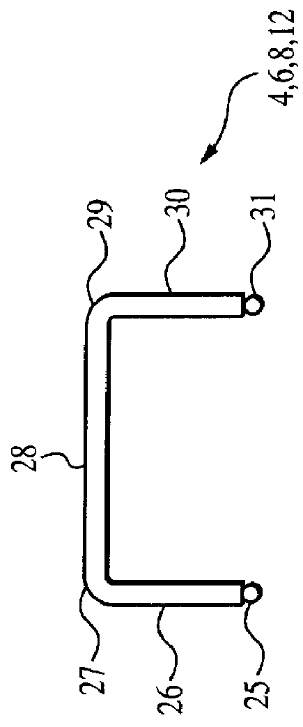
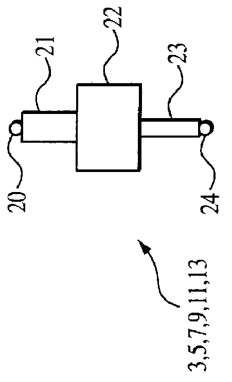
The composition of each radiator element 3, 5, 7, 9, 11 and 13 (and any intervening radiator elements) will be described in detail below with reference to FIG. 2A, while the composition of each delay line 4, 6, 8, and 12 (and any intervening delay line...


PUM


Abstract

A frequency-scan traveling wave antenna receives radio frequency (RF) energy at an input port, passes the energy through a quarter wave transformer to a first radiator element in an array of radiator elements, each pair of radiator elements being connected by a respective delay line. Each radiator element includes an input port of known characteristic impedance connected to an impedance matching section which compensates for that element's radiated power. Each radiator element has an output port with a section of transmission line disposed between a main radiator section of said radiator element and said output port, and impedance matched to the output port. In one embodiment, each delay line includes a plurality of delay line sections, with adjacent delay line sections being mutually perpendicular. In a second embodiment, each delay line includes a plurality of delay line sections disposed in meandering form.

Description

BACKGROUND OF THE INVENTION1. Field of the InventionThe present invention generally relates to a frequency-scan traveling wave antenna, and more particularly to a frequency-scan traveling wave antenna which operates at frequencies in the millimeter wave range.2. Description of the Prior ArtFrequency-scan traveling wave antennas are known in the art. Typically, uses of such antennas include their use in collision avoidance radar and in imaging radar. However, such frequency-scan traveling wave antennas are burdened by disadvantages, and those disadvantages adversely affect the quality of their performance. This interferes with the use of such antennas as an effective component of collision avoidance radar systems and imaging radar systems.Problems with traveling wave antennas of the prior art include the following: inferior radiating element design, inadequate impedance match, insufficient power weighting accuracy, and inferior phase coherence across an array.Accordingly, there is a ...

Claims


Application Information

Patent Timeline
Patent Type & Authority Patents(United States)
IPC IPC(8): H01Q11/04H01Q21/00H01Q3/22H01Q9/04H01Q11/00H01Q21/08
CPCH01Q3/22H01Q9/0407H01Q11/04H01Q21/0075H01Q21/08
Inventor KOSCICA, THOMASHUYNH, DUC
Owner UNITED STATES OF AMERICA
Why Eureka
Try Eureka