Eureka AIR delivers breakthrough ideas for toughest innovation challenges, trusted by R&D personnel around the world.

Log-polar signal processing

a technology of log-polar signal and processing method, which is applied in the field of log-polar signal processing, can solve the problems of not being able to predict the level of amplification required, and being difficult to achieve the resolution of the a/d-conversion process, etc., and achieves low cost and high precision.

Inactive Publication Date: 2001-04-17
TELEFON AB LM ERICSSON (PUBL)
View PDF7 Cites 72 Cited by
  • Summary
  • Abstract
  • Description
  • Claims
  • Application Information

AI Technical Summary

Benefits of technology

The advantages afforded by the inventive method and inventive arrangement reside in the solution of a troublesome problem within the field of radio communications, in a technically uncomplicated manner, therewith achieving high precision at low costs.

Problems solved by technology

The aforesaid, known solutions have practical limitations with respect to the possibilities of handling the dynamic ranges of the signals.
In the case of a receiver which must necessarily accept random transmission of data in the form of bursts from different transmitters, it is not possible, however, to predict the level of amplification required, when applying this method.
A further drawback, applicable to both of the aforesaid methods, resides in limited resolution during the A / D-conversion process.
Consequently, a signal beneath 20 mV will remain totally undiscovered, while a signal of 320 mV will only be digitalized to a resolution of 4 bits, which is perhaps insufficient for subsequent signal processing.
If a 4 bit resolution is nevertheless acceptable, the range in which the signals can be processed will be 16:1 or 24 dB, which is a very poor dynamic range in the case of radio applications.
Radar receivers are typical examples of systems in which it is impractical to use automatic amplification control for the purpose of maintaining the receiver output within narrow limits, this impracticability being due to a number of unknown parameters, for instance such parameters as the distance to the reflecting object, the size of said object and the duration of the pulse.
The method of digitalizing the detected output signal for subsequent numeric processing of the signal in an arrangement according to the aforegoing is insufficient when handling arbitrary radio signals, since the complex vector nature of the arbitrary radio signal will be lost in such a sequential detecting process.

Method used


Image

  • Log-polar signal processing
  • Log-polar signal processing
  • Log-polar signal processing

Examples


Embodiment Construction

Described in the following is a novel method of digitalizing composite signals and an arrangement for carrying out the method. A complex number can be expressed either in cartesian (x,y) form or in polar (R, THETA) form. Translation between these two forms can be effected readily with the aid of the equations X=R cos (THETA); Y=R sin (THETA).

The log polar form (r, THETA) in which r=log (R) can be advantageously used as an alternative to the two forms aforesaid. The following transformation will then apply: (x,y)=exp(r+j THETA); (rl, THETA)=log(x,y).

These equations show that when having a value on the logarithm of the amplitude of the complex vector (r) and a value on the angle (THETA) of the complex vector, it is possible to restore the cartesian components of the complex vector when so desired.

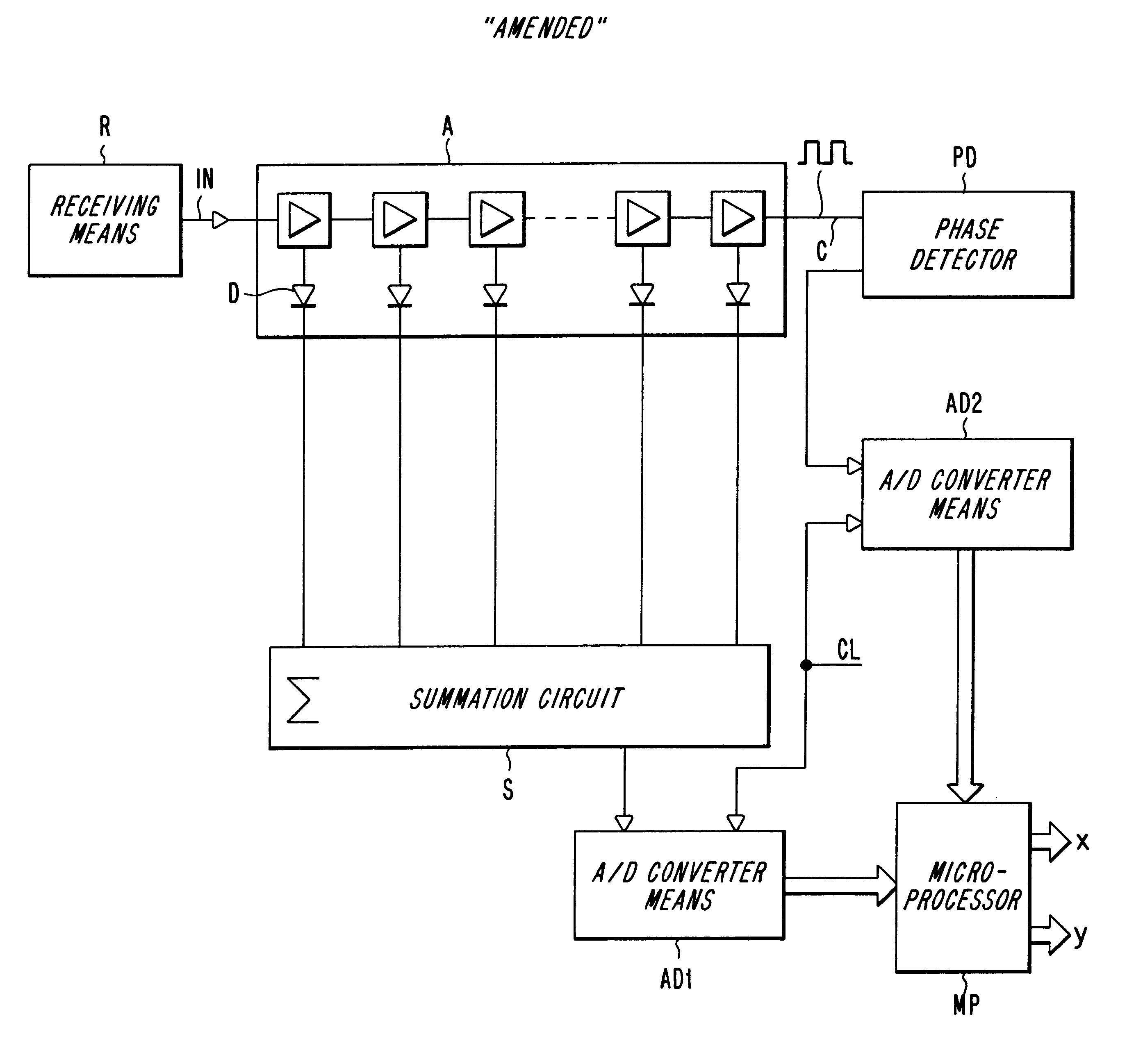
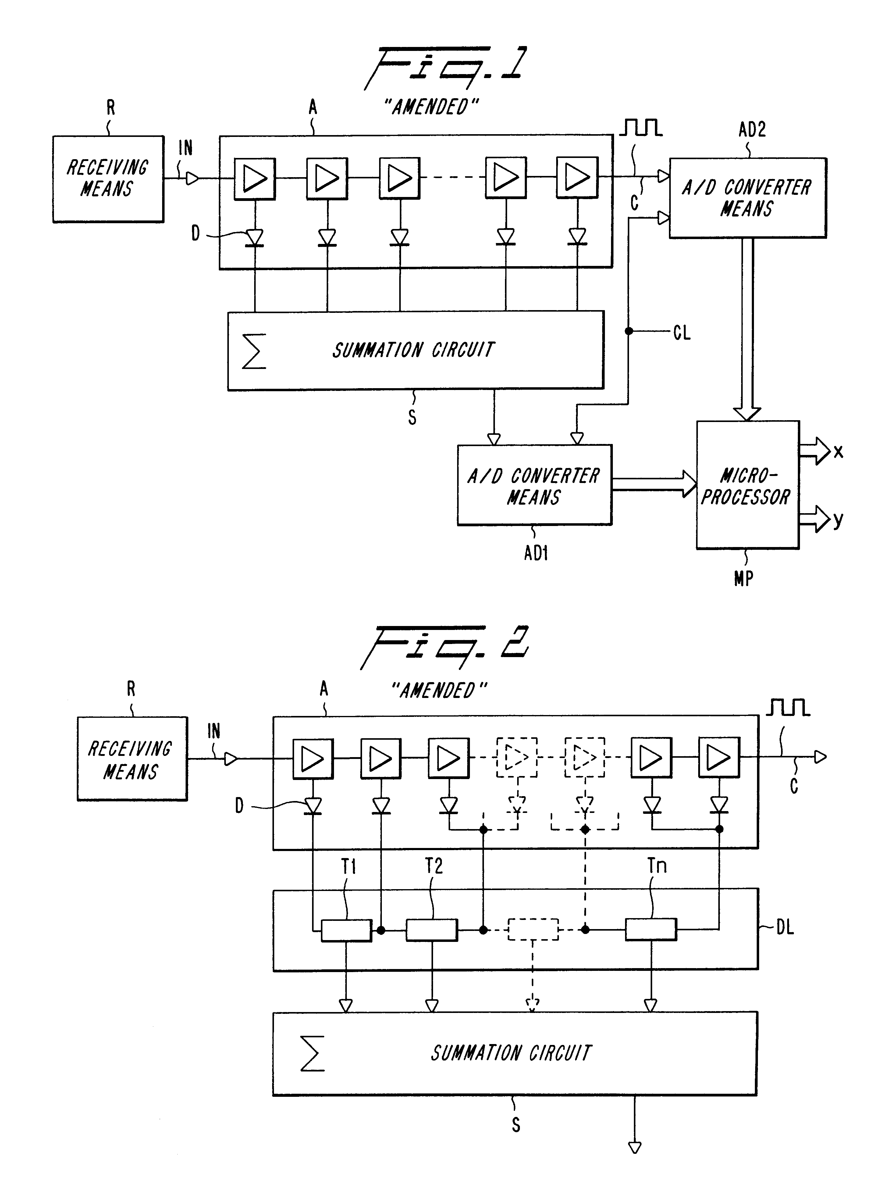
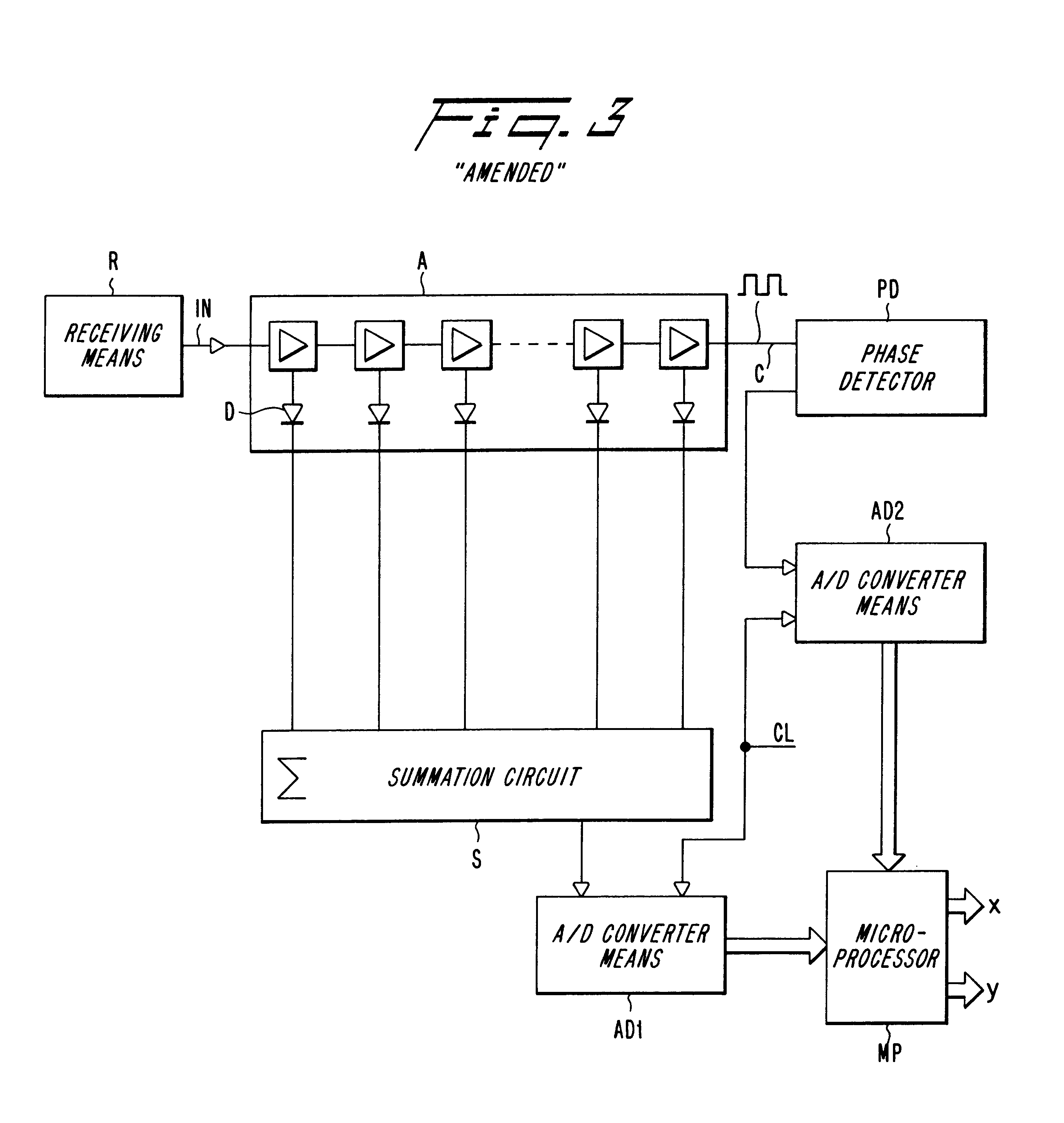
The inventive digitalizing arrangement for complex signals having wide dynamic ranges utilizes the principle illustrated in FIG. 1. The signal to be processed is converted to an appropriate i...


PUM


Abstract

The invention relates to a method and an arrangement intended for radio communication systems and effective in digitalizing and subsequently processing numerically arbitrary radio signals. The signals are represented by composite (complex) vectors which have been subjected to disturbances in the system, such that information in the signals has been lost. This information is restored in its entirety when practising the present invention. For the purpose of solving this problem, the inventive digitalizing arrangement includes a multistage logarithmic amplifier chain (A) in which each stage is connected to a separate detector (D), the output signals of which are added in an adder. The adder output signals are then transmitted to a first A / D-converter (AD1) for digitalizing and converting the amplitude components of the signal. At the same time, the undetected signal from the saturated output stage in the amplifier chain is transmitted to a second A / D-converter for digitalizing and converting the phase components of the signal. The digital values obtained on the outputs of the AD-converters (AD1, AD2) are applied to different inputs of a digital signal processor (MP) for numerical processing of the pairwise received digital values in a manner such as to restore the complete vector characteristic of the signal.

Description

TECHNICAL FIELDThe invention relates to an improved method and arrangement of apparatus for digitalizing and subsequently processing numerically radio signals in those instances when the levels of said signal can vary over a wide dynamic range and where the level values cannot be readily determined beforehand with the aid of sampling techniques.BACKGROUND ARTIt is always possible to represent an arbitrary radio signal as a sequence of composite (complex) vectors. The real and imaginary parts of the vector sequence correspond to bipolar amplitude modulation (double side band suppressed carrier AM) of a cosinusoidal and sinuosidal carrier wave respectively (quadrature carriers). When wishing to process a radio signal numerically using digital arithmetic implemented in either specific hardware logic or in software on a computer, microprocessor or some other programmable apparatus, it is first necessary to convert the signal in to numerical form with the aid of a A / D-converter (Analogue...

Claims


Application Information

Patent Timeline
Patent Type & Authority Patents(United States)
IPC IPC(8): H03G7/00H04L27/22H04L27/38H03D1/00H03M1/12H04L27/01H04L27/06
CPCH03G7/001H03G7/007H04L27/22H04L27/38H04L27/3809H04L27/06
Inventor DENT, PAUL WILKINSON
Owner TELEFON AB LM ERICSSON (PUBL)
Why Eureka
Eureka Blog
Learn More