Vial filling apparatus

a filling apparatus and container technology, applied in the direction of packaging goods, furniture, charge manipulation, etc., can solve the problems of finished packages becoming contaminated and unusable, time-consuming and expensive maintenance of the filling apparatus and the clean room, and contamination in the clean room environmen

Inactive Publication Date: 2001-12-18
ROBERT BOSCH PACKAGE TECH
View PDF81 Cites 69 Cited by
  • Summary
  • Abstract
  • Description
  • Claims
  • Application Information

AI Technical Summary

Problems solved by technology

It is difficult, time consuming and expensive to maintain the container filling apparatus and the clean room in a low level contamination.
Conversely, the contamination of any single component may cause the finished package to become contaminated and unusable.
The primary source of contamination in a clean room environment is from individuals within the room who operate and / or monitor the filling apparatus.
Equipment operators or other people that may enter the sterile environment contribute high levels of contaminants to the environment both in the form of microorganisms and particles.
This resulted in a number of problems, the primary of which were inaccessibility to and extreme difficulty in cleaning and sterilizing the zone interior including the housed components, and the sealing of the components that pass from the inside to the outside of the sterilize zone.
When the concept was proposed to surround the upper clean space with an isolation barrier, several problems arose.
First, the horizontal table top was relatively wide and, when surrounded by a barrier, would not allow for access to all points within the clean space with conventional techniques using glove port access.
Because the conventional horizontal table top was large and flat, not allowing for good drainage, and since many mechanical devices pass through from the upper clean zone, now the sterile zone inside the isolator, to the lower mechanical space, the problems of drainage and sealing of the bottom of the sterile zone became a major problem.

Method used


Image

  • Vial filling apparatus
  • Vial filling apparatus
  • Vial filling apparatus

Examples


Embodiment Construction

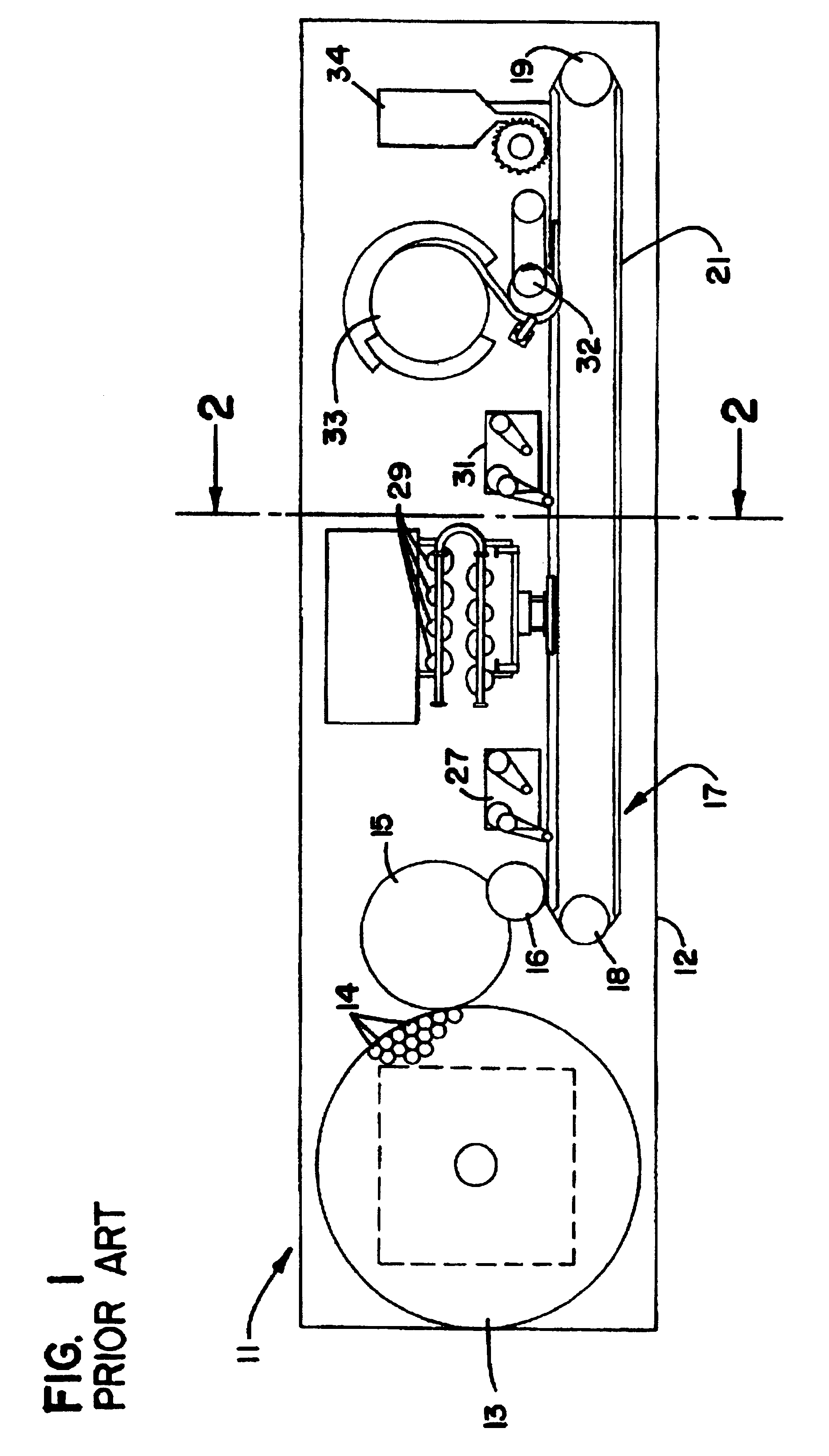
With initial reference to FIGS. 1, 2 and 6, a typical prior art filling apparatus is represented generally by the numeral 11. Apparatus 11 comprises a large table or frame 12 that is horizontally disposed and supports all of the various components of apparatus 11. With particular reference to FIG. 1, these components include an accumulator disk 13 which is filled with a plurality of vials 14 received from a conveyor not shown. Vials 14 are transferred from accumulator disk 13 to a transfer disk 15, and a star wheel 16 individually picks up vials 14 from the transfer disk 15 and carries them to a vial conveyor 17.

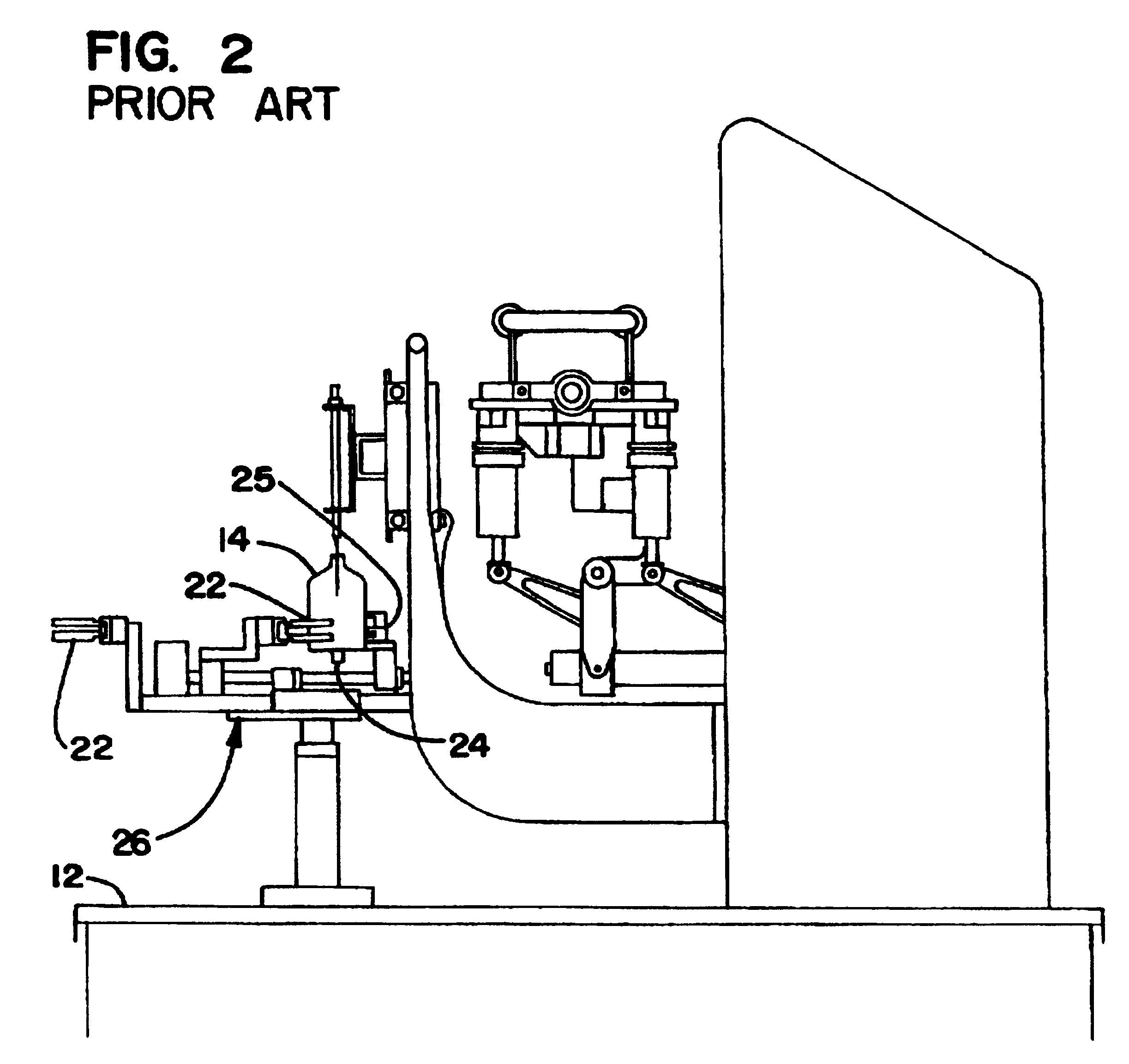
With reference to FIGS. 1, 2 and 6, conveyor 17 includes drive sprockets 18, 19 at opposite ends with a sprocket type conveyor belt 21 operably connected therebetween. A plurality of cleats 22 are mounted on and carried by conveyor belt 21, each having a V-shaped frontal recess 23 that is capable of receiving and carrying vials 14 of different diameter. The sequentially carr...


PUM

PropertyMeasurementUnit
included angleaaaaaaaaaa
lengthaaaaaaaaaa
widthaaaaaaaaaa

Abstract

Apparatus for filling sterile containers is disclosed which defines an elongated but narrow sterile zone in which a number of operating stations are disposed. An elongated vertical wall is carried by an elongated frame and a cabinet type enclosure cooperates with the vertical wall to define the sterile zone. The plurality of operating stations are disposed in sequential relation over the length of the sterile zone, and an elongated container conveyor is disposed within the sterile zone to convey the containers through the plurality of operating stations. The conveyor is vertically oriented, consisting an endless belt mounted on end wheels that rotate on horizontal axes. Each of the operating stations includes an operating portion disposed within the sterile zone. Actuating means are included for each of the operating stations as well as the elongated conveyor, each of which is disposed outside the sterile zone. Connecting means operabably connect each of the actuating means outside the sterile zone through the vertical wall to the associated operating station within the sterile zone. By orienting the conveyor vertically and disposing the various actuating means outside the sterile zone in side-by-side relation, the effective width of the sterile zone is significantly reduced. As a result, the sterile zone is more easily accessed, and also more easily drained after washdown operations. In addition, the sterile zone of reduced size results in an apparatus that much easier to manufacture and maintain in a sterile state.

Description

BACKGROUND OF THE INVENTIONThe invention broadly relates to container filling apparatus and is specifically directed to an improved apparatus for rapidly filling containers in a sterile environment.Many pharmaceutical preparations produced by the pharmaceutical industry are dispensed in relatively small containers. Among these are injectable drugs and medicines which, by the nature of their use must be dispensed with a high level of sterility assurance. Elaborate techniques and apparatus are employed to maintain this high level of sterility.To limit contamination, current container filling apparatus, which tends to be quite large, is placed in a clean room environment with the apparatus operators required to wear sterile attire, including gowns, gloves, headwear, masks and the like. The clean room itself must be maintained in a low contamination level, with conventional precautions taken as the operating personnel enter, observe and make adjustments to the equipment and leave. The a...

Claims


Application Information

Patent Timeline
Patent Type & Authority Patents(United States)
IPC IPC(8): B65B55/02B65B31/02B65B55/04B65B59/02
CPCB65B55/025B65B55/027
Inventor JAGGER, THEODORE W.
Owner ROBERT BOSCH PACKAGE TECH
Why Eureka
Try Eureka