Cutting insert for cutting and grooving tools

a cutting insert and tool technology, applied in the direction of cutting inserts, manufacturing tools, shaping cutters, etc., can solve the problems of high production cost, high difficulty, and tangled chips that may wrap around the workpiece or the tool, and achieve the effect of less costly, efficient and safe chips, and less tangled chips

Inactive Publication Date: 2002-03-19
SANDVIK INTELLECTUAL PROPERTY AB
View PDF14 Cites 34 Cited by
  • Summary
  • Abstract
  • Description
  • Claims
  • Application Information

AI Technical Summary

Benefits of technology

In accordance with the present invention, a dimpled chipbreaker and the confining walls thereof are designed so as to form the chip narrower than the groove such that more efficiently manageable safe chips can be obtained. Chip disposal should become safer, more efficient and less costly. With such inserts, it should become possible to generate a finished groove in one pass of the workpiece, such as a crankshaft.

Problems solved by technology

It is not unusual that in such operations the chips may become tangled and wrap around the workpiece or the tool.
This creates problems in subsequent operations, especially if automated workpiece handling equipment is involved.
These difficulties are compounded when it comes to camshaft or crankshaft turning where several grooves are generated in one operation.
The end result is usually high production costs due to expansive machine downtime to clear chips or repair tools.

Method used


Image

  • Cutting insert for cutting and grooving tools
  • Cutting insert for cutting and grooving tools
  • Cutting insert for cutting and grooving tools

Examples


Embodiment Construction

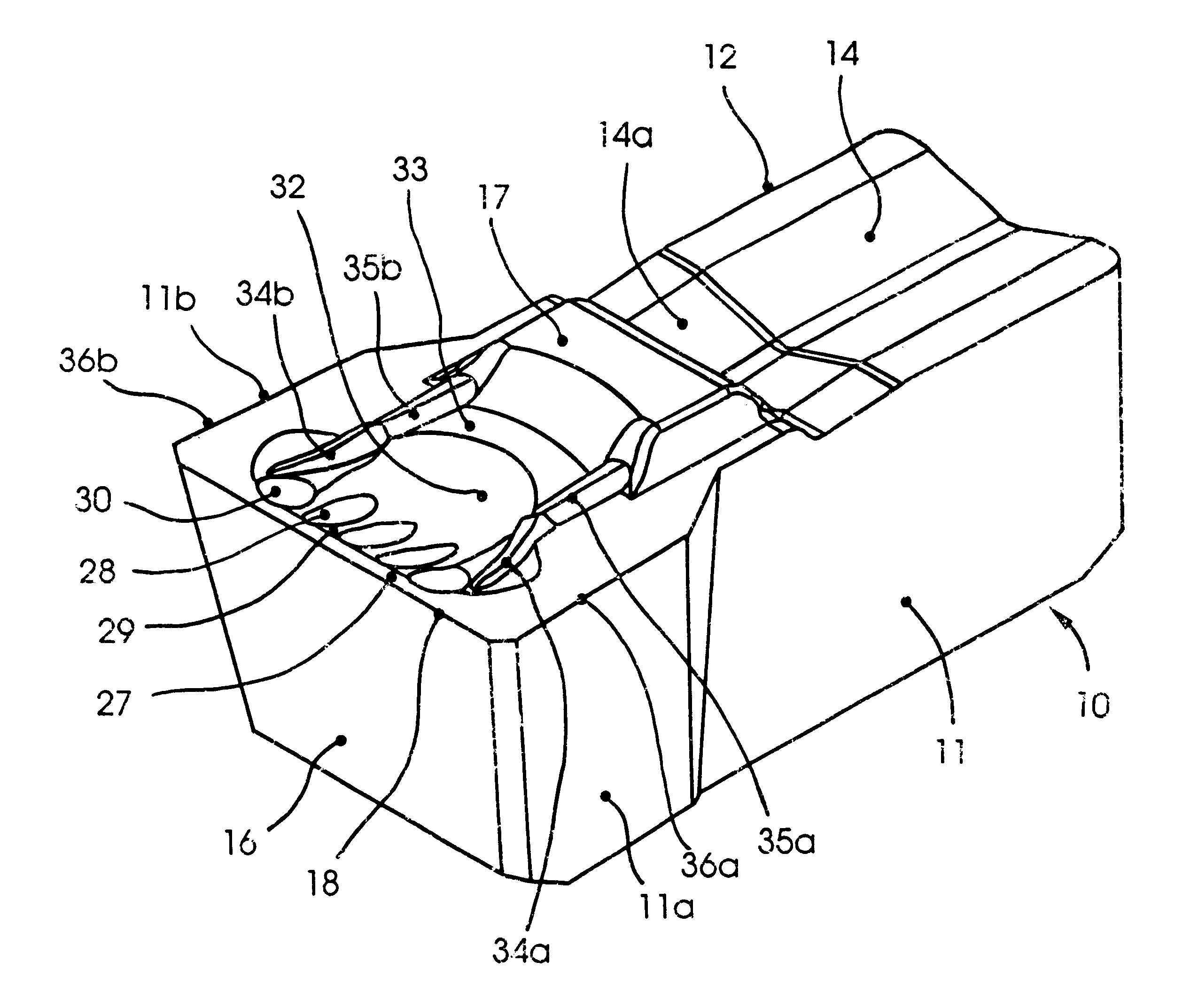
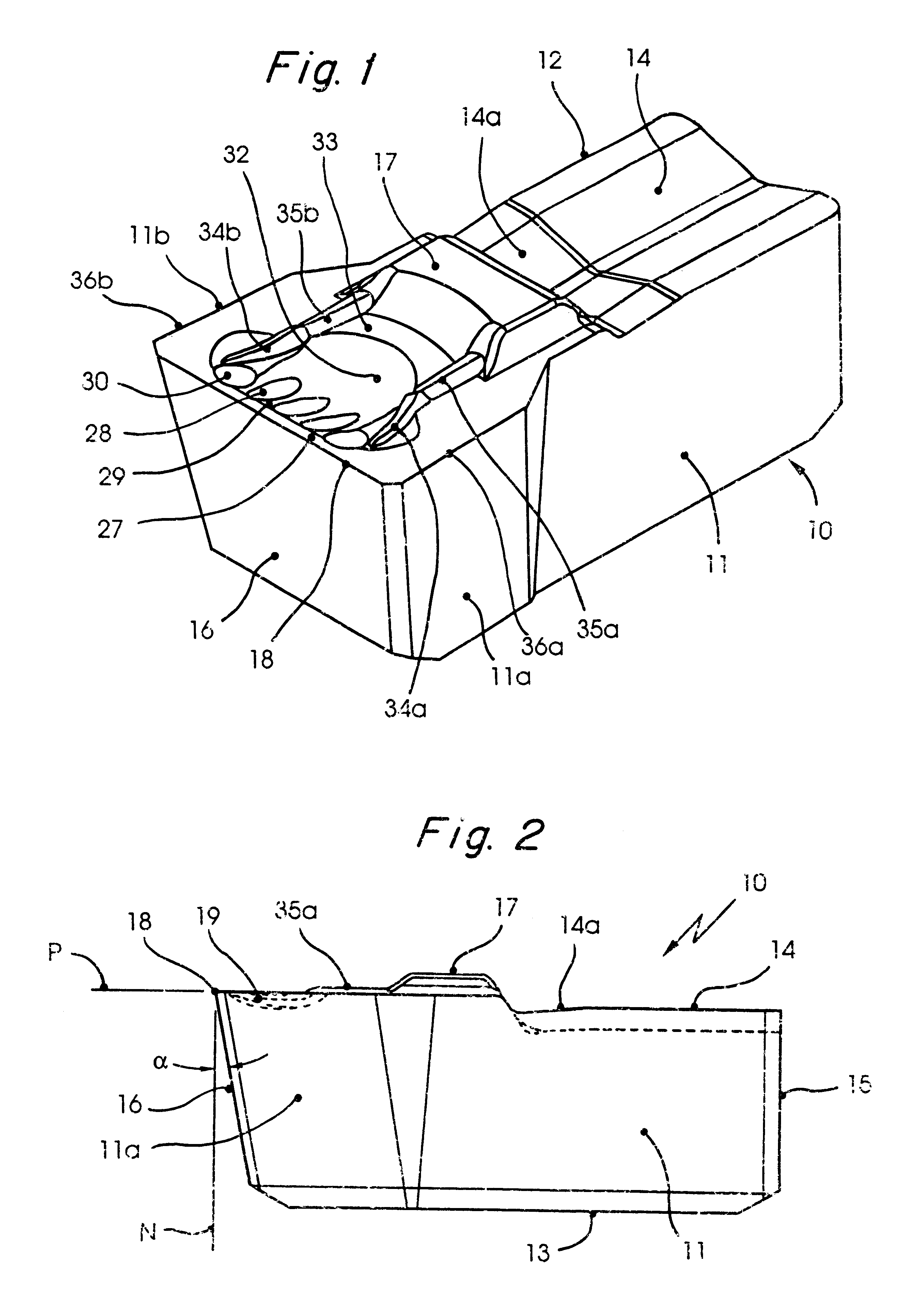
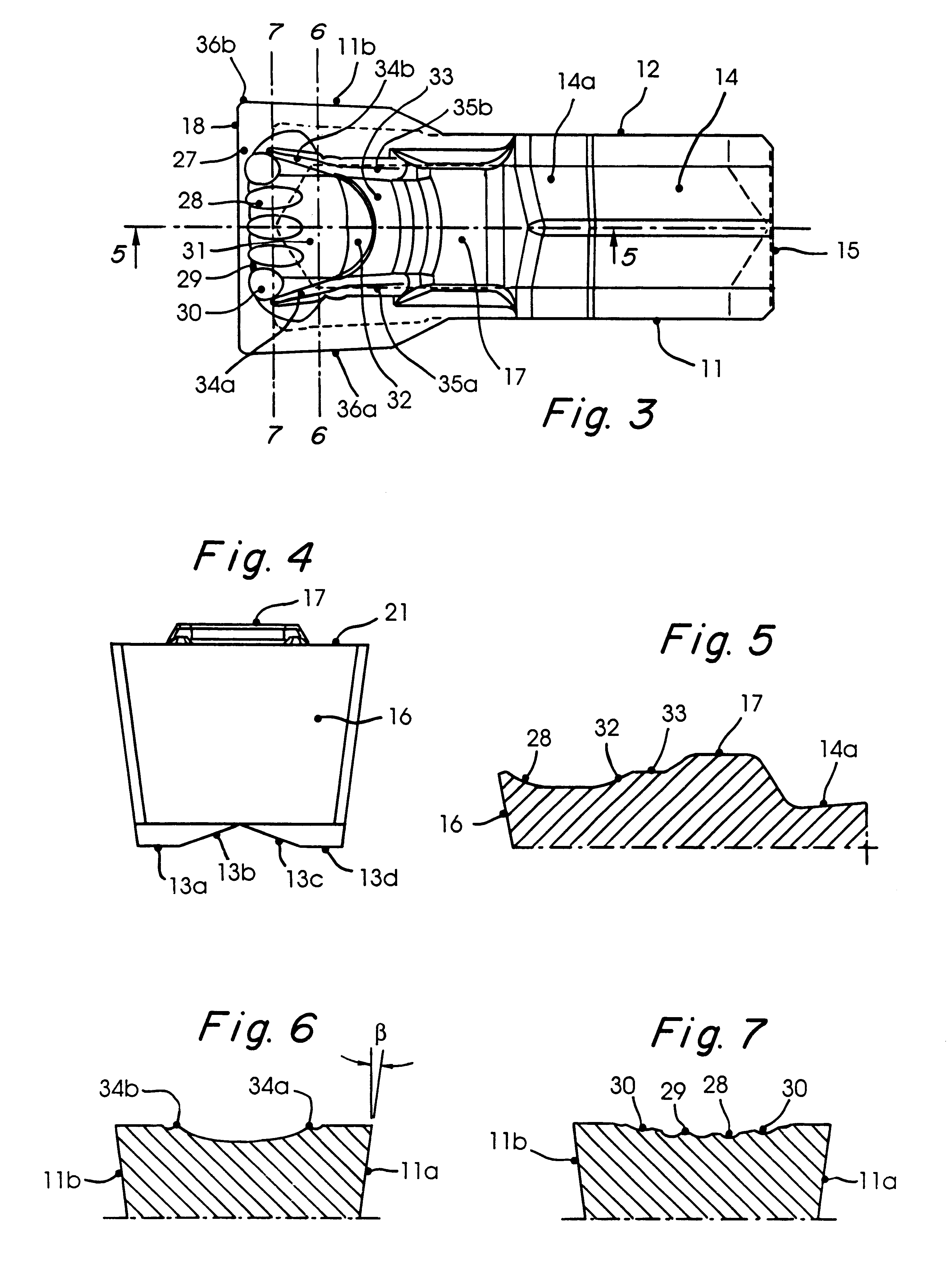
An insert 10 according to the invention is shown in the drawing figures. The insert is in the shape of a polygonal body of generally parallepipedic shape. It comprises two mainly plane-parallel side surfaces 11, 12, opposed top and bottom surfaces 14 and 13, respectively, two end surfaces 15, 16, and a shoulder 17. The front portion of the insert is provided with a main cutting edge 18 and a chip forming area 19. The insert is intended to be secured to a holder body 20 (FIG. 8) provided with an integral clamping arm 21. The top surface 14 is broken at the vicinity of the shoulder 17 so that an upper surface portion 14a forms an acute angle with the remainder of the surface 14.

With reference to FIG. 8, the insert 10 is intended to be removably held in a holder, which includes the holder body 20 having an integral clamping arm 21 in a front portion 22 of the holder body 20 and an insert receiving recess 23 in which the insert 10 is to be located. The insert receiving recess 23 communi...


PUM

PropertyMeasurementUnit
distanceaaaaaaaaaa
lengthaaaaaaaaaa
depthaaaaaaaaaa

Abstract

The present invention relates to a turning insert that comprises a generally rectangularly shaped body having a front end surface with a main cutting edge at the intersection between the front end surface and an upper land area. A chipforming area is provided in the forward portion of the upper surface and is shaped in the form of a number of distinctly provided recesses and ridges in order to promote improved chip control and to obtain narrower chips in grooving operations.

Description

BACKGROUND AND SUMMARY OF THE PRESENT INVENTIONThe present invention relates to a cutting insert for turning and grooving tools, primarily for grooving operations in metal workpieces. The insert could also be useful for cutting off rods, tubes or other rotationally symmetrical details. Such cutting inserts are provided with a cutting edge formed by the transition between the top surface or rake surface of the insert and its forward clearance face.In metal cutting operations, the breaking of the chip and the shape of the chip are often of great importance for an undisturbed production. In modem, high production machines and tools, there is great demand for an efficient chip removal and good chip control. This is of special importance in such high-production machines in which a series of different tools are performing different operations in a continuous sequence. It is not unusual that in such operations the chips may become tangled and wrap around the workpiece or the tool. This cre...

Claims


Application Information

Patent Timeline
Patent Type & Authority Patents(United States)
IPC IPC(8): B23B27/04B23B27/00
CPCB23B27/045B23B2205/02Y10T407/25Y10T407/245Y10T407/2288B23B2260/124
Inventor LINDSTEDT, LARS
Owner SANDVIK INTELLECTUAL PROPERTY AB
Why Eureka
Try Eureka