Voltage regulator that operates in either PWM or PFM mode

a voltage regulator and pwm technology, applied in the field of voltage regulators, can solve the problems of impracticality of pfm mode and lower and achieve the effect of reducing the gate-drive power dissipation of pfm mode and improving efficiency

Inactive Publication Date: 2002-03-26
MICREL
View PDF11 Cites 90 Cited by
  • Summary
  • Abstract
  • Description
  • Claims
  • Application Information

AI Technical Summary

Benefits of technology

A PFM mode of voltage regulation provides better efficiency at small output current levels than does a PWM mode. First, a PFM mode requires .[.a.]. fewer turn-on transitions to maintain a constant output voltage than does a PWM mode of voltage regulation, thus resulting in a lower gate-drive power dissipation for PFM mode. Second, since a PFM mode can be achieved with a much simpler control circuit having fewer components, the power dissipation in the control loop of a PFM mode is less than that of the control loop of a PWM mode.

Problems solved by technology

First, a PFM mode requires .[.a.]. fewer turn-on transitions to maintain a constant output voltage than does a PWM mode of voltage regulation, thus resulting in a lower gate-drive power dissipation for PFM mode.
However, when the output current reaches a moderate level, a PFM mode of voltage regulation becomes impractical, since the maximum output current available from a PFM mode is generally much less than that available from a PWM mode.

Method used


Image

  • Voltage regulator that operates in either PWM or PFM mode
  • Voltage regulator that operates in either PWM or PFM mode
  • Voltage regulator that operates in either PWM or PFM mode

Examples


Embodiment Construction

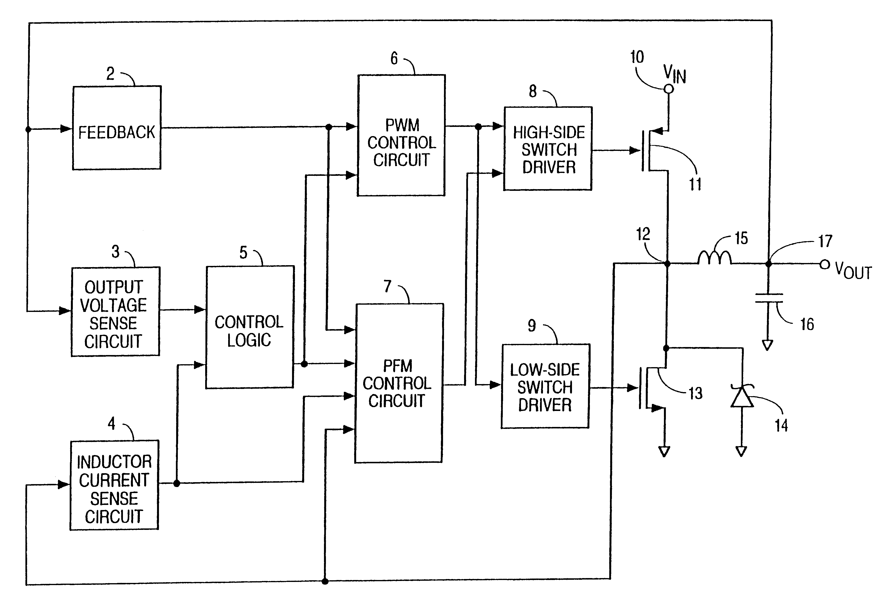
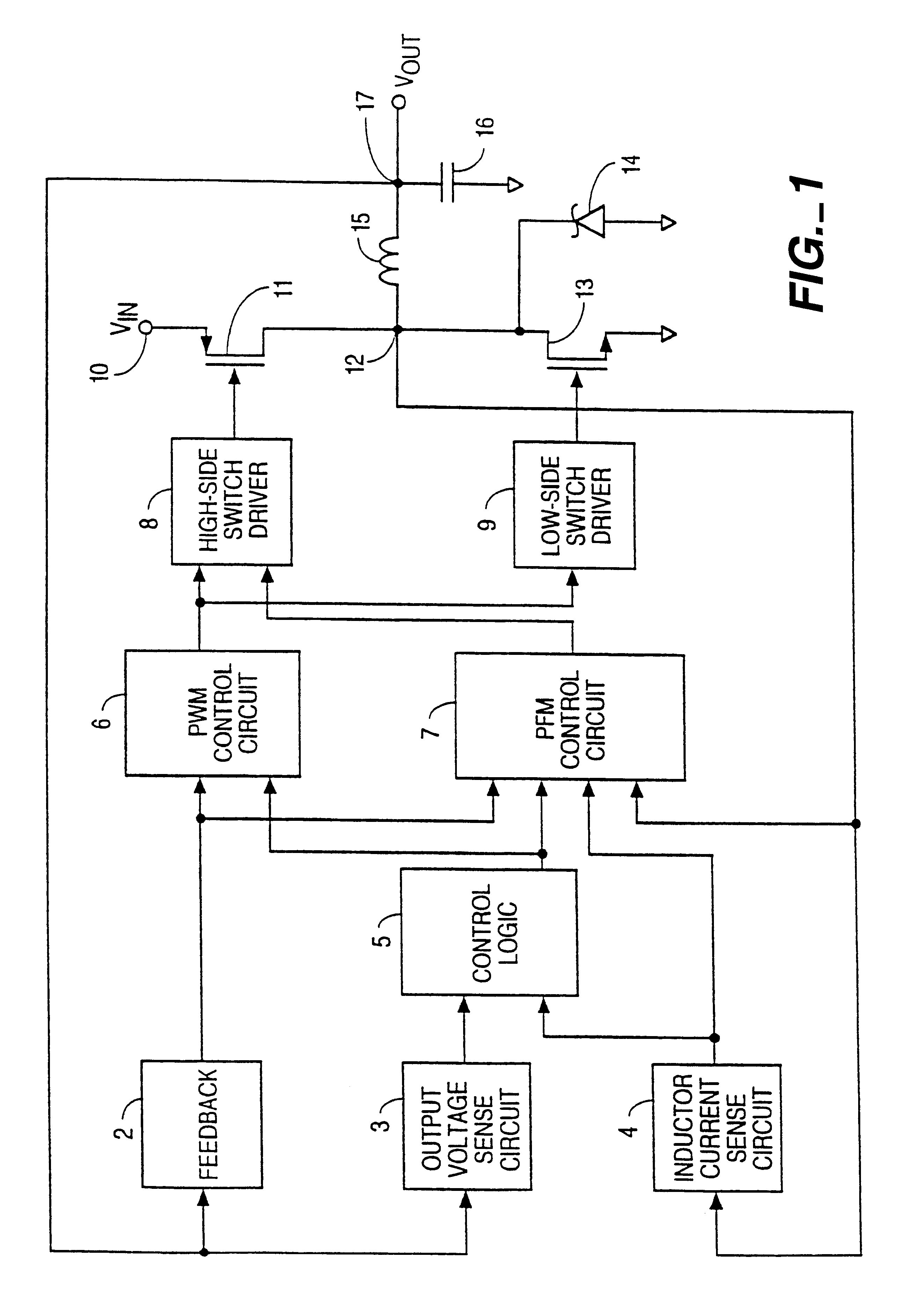
FIG. 1 is a simplified block diagram of an embodiment of the present invention. The voltage regulator of FIG. 1 includes a feedback circuit 2, output voltage sensing circuit 3, inductor current sensing circuit 4, control logic circuit 5, PWM control circuit 6, PFM control circuit 7, high-side switch driver 8, low-side switch driver 9, input terminal 10, high-side switch 11, switching node 12, low-side switch 13, schottky diode 14, inductor 15, capacitor 16, and output terminal 17.

High-side switch 11 is preferably a P-channel MOSFET that has a first terminal connected to input terminal 10 and a second terminal connected to a terminal (switching node 12) of inductor 15. The other terminal of inductor 15 is connected to output terminal 17.

PWM control circuit 6, which includes a PWM signal generator, has an output terminal connected to a first input terminal of the high-side switch driver 8. The output terminal of PWM control circuit 6 is also connected to the low-side switch driver 9. ...


PUM


Abstract

A switching voltage regulator achieves high efficiency by automatically switching between a pulse frequency modulation (PFM) mode and a pulse-width modulation (PWM) mode. Switching between the modes of voltage regulation is accomplished by monitoring the output voltage and the output current, wherein the regulator operates in PFM mode at small output currents and in PWM mode at moderate to large output currents. PFM mode maintains a constant output voltage by forcing the switching device to skip cycles when the output voltage exceeds its nominal value. In PWM mode, a PWM signal having a variable duty cycle controls the switching device. A constant output voltage is maintained by feedback circuitry which alters the duty cycle of the PWM signal according to fluctuations in the output voltage.

Description

FIELD OF THE INVENTIONThe present invention relates to a voltage regulator. More specifically, the present invention relates to a high efficiency switching voltage regulator capable of operating in either one of two modes.BACKGROUND OF THE INVENTIONTypically, voltage regulator circuits provide a constant output voltage of a predetermined value by monitoring the output and using feedback to keep the output constant. In a typical pulse width modulation (PWM) regulator circuit, a square wave is provided to the control terminal of the switching device to control its on and off states. Since increasing the on time of the switching device increases the output voltage, and vice versa, the output voltage may be controlled by manipulating the duty cycle of the square wave. This manipulation is accomplished by a control circuit which continually compares the output voltage to a reference voltage and adjusts the duty cycle of the square wave to maintain a constant output voltage.When the switc...

Claims


Application Information

Patent Timeline
Patent Type & Authority Patents(United States)
IPC IPC(8): H02M3/156H02M3/04H02M3/158
CPCH02M3/156H02M3/1588Y02B70/10H02M1/0032
Inventor BITTNER, HARRY J.
Owner MICREL
Why Eureka
Try Eureka