Leadframe with heat dissipator connected to S-shaped fingers

a technology of heat dissipator and lead frame, which is applied in the direction of solid-state devices, electric devices, basic electric elements, etc., can solve the problems of reducing the life and therefore the reliability of the device, reducing the efficiency of the device, and reducing the life of the device. , to achieve the effect of reducing manufacturing costs and simplifying the mold

Inactive Publication Date: 2002-05-21
STMICROELECTRONICS SRL
View PDF11 Cites 47 Cited by
  • Summary
  • Abstract
  • Description
  • Claims
  • Application Information

AI Technical Summary

Benefits of technology

Within the scope of this aim, a particular object of the present invention is to provide an improved leadframe which has such a configuration that no pushers which pass through the resin and cause interruptions therein are required during the molding of the plastic case.
In particular, an object of the present invention is to provide a leadframe by virtue of which, after the molding of the plastic case, the inner face of the dissipator which is in contact with the chip is completely covered by the resin, so that it is protected against external contaminating agents, avoiding thus the deposit of resin residues on the outer side of the dissipator.
An important object of the present invention is to provide a leadframe which allows to obtain a significant simplification in the mold for the plastic case, with a reduction in manufacturing costs.

Problems solved by technology

However, this solution is disadvantageous.
However, the exposure of even only part of the inner face of the dissipator is unwanted, since said face is not protected against external influences during the further manufacturing steps (e.g. nickel-plating for the coating of the leads), and in particular it facilitates the penetration of humidity inside the package, reducing the life and therefore the reliability of the device.
Due to the presence of the pushers, the mold furthermore has a relatively complicated and therefore expensive configuration.

Method used


Image

  • Leadframe with heat dissipator connected to S-shaped fingers
  • Leadframe with heat dissipator connected to S-shaped fingers
  • Leadframe with heat dissipator connected to S-shaped fingers

Examples


Embodiment Construction

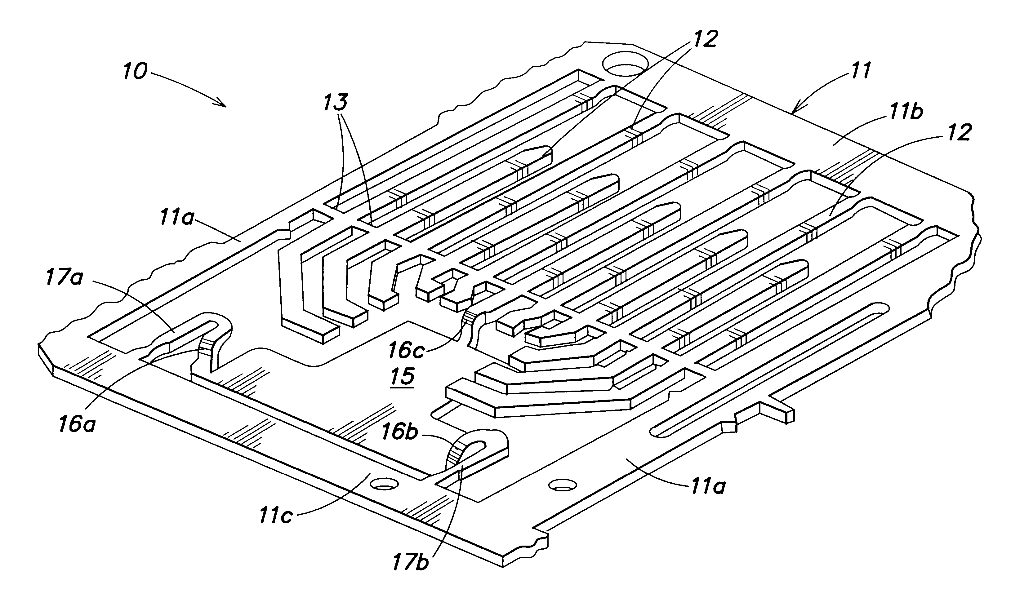
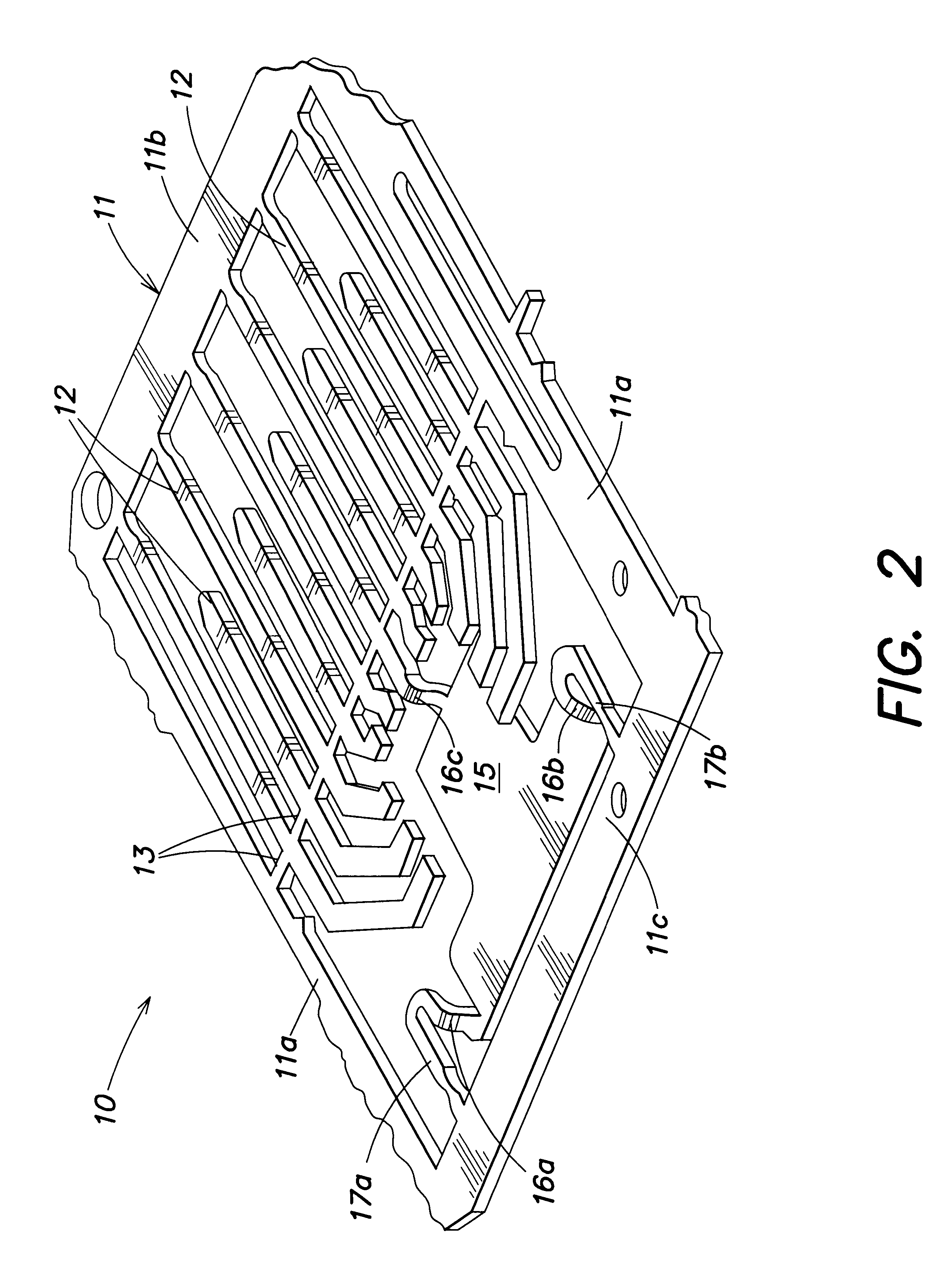
With reference to FIG. 2, the leadframe according to the invention is generally indicated by the reference numeral 10 and is part of a strip which comprises for example ten of said leadframes, all identical and arranged side by side. In detail, the leadframe comprises a frame 11 which, according to the invention, extends along a substantially rectangular closed line which defines the outer perimeter of the leadframe. The sides of the frame indicated by 11a are in common with the adjacent leadframes (not illustrated in the figure) of the same strip. The frame 11 supports the leads 12 (eleven in the illustrated example), some of which are connected to the side 11b of the frame at their tip, whereas all the leads are connected to an intermediate portion of the sides 11a of the frame by means of segments 13 which define an interconnection line. Similarly to the prior art, the lead interconnection segments 13 are intended to be removed, together with the frame 11, after the execution of ...


PUM


Abstract

An improved leadframe for packages of integrated power devices which, by virtue of its configuration, allows to press the dissipator on the bottom of the shell during the molding of the plastic case, without the dissipator having exposed portions of its inner face (which is in contact with the chip). In order to achieve this, the leadframe according to the invention comprises a monolithic body which defines a perimetric frame, the leads and the dissipator. The dissipator extends in a depressed plane with respect to the frame and is connected to the frame and to the leads in at least three step-like points which are mutually spaced and non-aligned. During the molding of the plastic case, a pressure is exerted on the frame and is transmitted to the dissipator by the three step-like points, so that the dissipator is effectively pressed flat against the bottom of the mold without using pushers which pass through the plastic case.

Description

BACKGROUND OF THE INVENTIONThe present invention relates to an improved leadframe for packages of integrated power devices. In particular, the present invention is related to medium-power integrated circuits.As is known, in the manufacture of integrated power devices, the chip of semiconductor material which integrates the electronic components is welded to a dissipator which is connected to a leadframe. Generally, the dissipator, which is thicker than the leadframe and is arranged on a different plane, is manufactured separately and is connected mechanically to the leadframe so that its face which is to be welded to the chip is directed toward the leads. Then, after the provision of the interconnections between the chip and the leads or terminals, a plastic case of epoxy resin, with a generally parallelepipedal shape, is molded on one face of the dissipator and completely embeds the chip. In particular, the plastic case only partially covers the face of the dissipator which is in c...

Claims


Application Information

Patent Timeline
Patent Type & Authority Patents(United States)
IPC IPC(8): H01L23/48H01L23/495
CPCH01L23/49503H01L23/49541H01L23/49568H01L2924/0002H01L2924/00
Inventor BOZZINI, PIERAMEDEOMARCHISI, GIUSEPPE
Owner STMICROELECTRONICS SRL
Why Eureka
Try Eureka