High precision component alignment sensor system

a sensor system and high-precision technology, applied in the direction of converting sensor output optically, instruments, measuring devices, etc., can solve the problems of high cost, difficult to achieve the very high degree of accuracy, and damage such as microcracking and other such components, so as to accurately determine the angular orientation and lateral position of components. , to achieve the effect of accurately determining the angular orientation of a componen

Inactive Publication Date: 2003-03-11
CYBEROPTICS
View PDF56 Cites 27 Cited by
  • Summary
  • Abstract
  • Description
  • Claims
  • Application Information

AI Technical Summary

Benefits of technology

It is an object of the invention to accurately and precisely determine angular orientation and lateral position of components for placement by a component placement machine.
It is an object of the invention to accurately determine angular orientation of a component to be placed by a component placement machine with an accuracy of better than 0.03 degrees.

Problems solved by technology

The striking of such components can cause damage such as microcracking and other such components.
It is also extremely difficult to achieve the very high degree of accuracy both as to angular orientation and lateral position that is required by the design rules in use in today's technology where lead spacing and widths are only 10-25 mils wide.
To accommodate different component sizes, six different sizes of jaws may be required which can lead to high expense.
However, light based systems of the past have had difficulty in achieving the high speed and high accuracy which is required for today's technology.
However, they are one of the most expensive of systems proposed and they require a deviation in the path of the quill from the bin to the TV station, and then to the work piece or circuit board which substantially slows the process.
In addition, it is sometimes difficult to distinguish the particular parameters of very small components being placed by such systems from the quill upon which the components are mounted.
However, it is difficult for such systems to handle the range of components that are placed and to achieve the accuracy required for alignment.
If a single photodetector system is designed large enough to detect shadow variations for a 2.0 inch part, as it must be, the fractional variation caused by rotation of a 0.02 inch part has such little effect on the total light intensity that it is virtually undetectable.
However, it is extremely difficult to mechanically align photodetectors to make such a measurement.
The uniformity of light must be precise and such a system cannot detect component lead positions since shadows of the leads are not distinguishable from shadows of the body of the component.
However, the degree of accuracy that can be achieved can be no more than the spacing of the individual laser sources one from the other.
This minimum spacing still would be too large for reliable component position detection.
The required physical spacing will also be negatively affected by diffraction effects to further limit accuracy of such a design.
Also, it is believed that the cost of such a system involving many laser sources would also be prohibitively expensive.

Method used


Image

  • High precision component alignment sensor system
  • High precision component alignment sensor system
  • High precision component alignment sensor system

Examples


Embodiment Construction

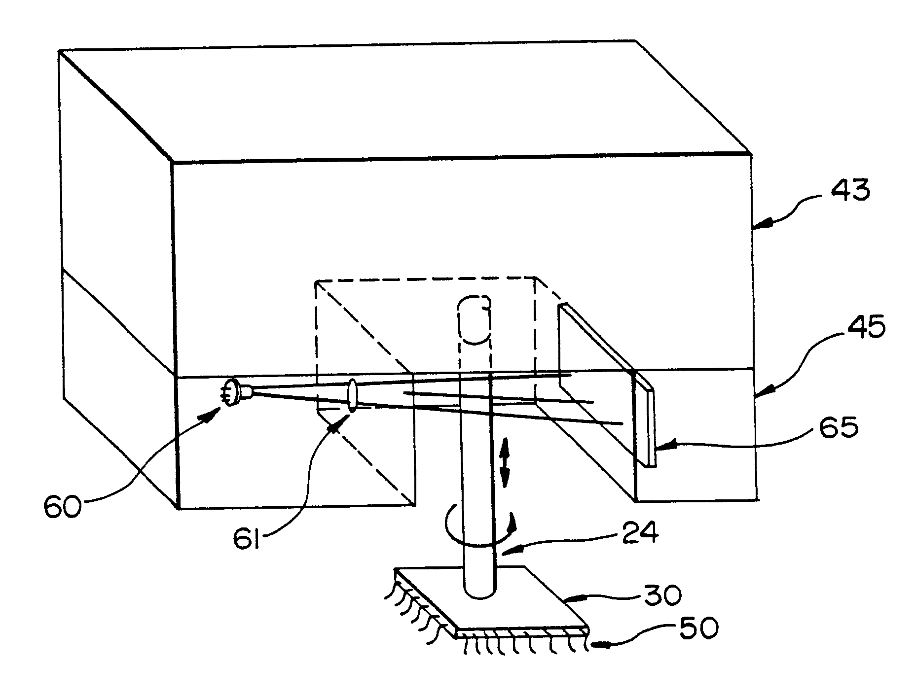
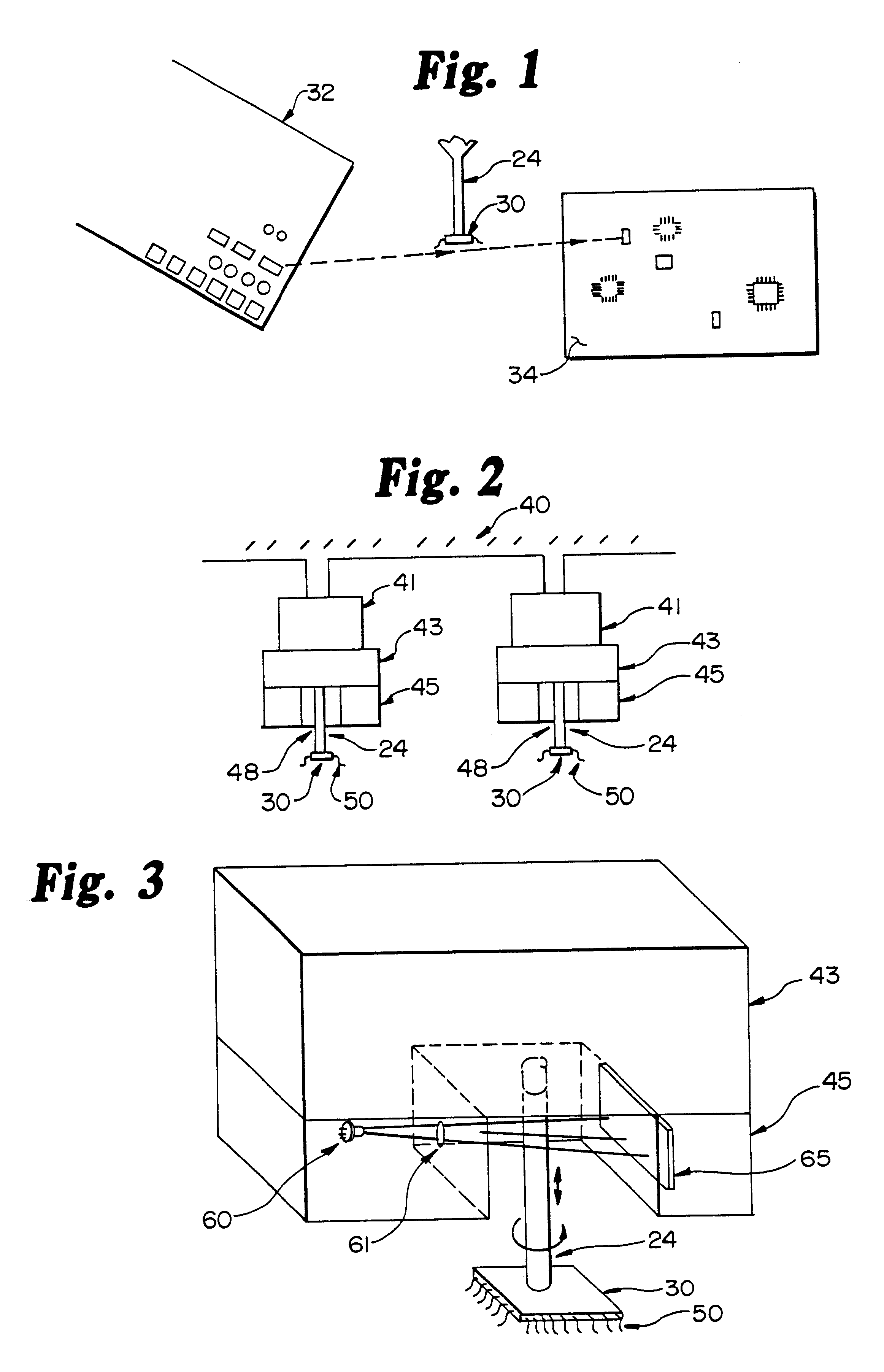
FIGS. 1 and 2 illustrate the general environment in which the invention is to be used. FIG. 1 illustrates in diagram form a typical surface mount component placement machine in which one or more vacuum quills 24 are used to sequentially pick up components 30 from predetermined bins 32, transport them as quickly as possible to a circuit board 34 or other surface upon which the component must be precisely aligned, and place the component 30 accurately at the desired location with the proper alignment of the leads 50 of the component 30 to a wiring layout which has been previously created on the circuit board 34. For high precision placement, an accuracy in angular alignment or orientation of 0.30 degress with positioning error in the X,Y plane of 0.001 inch is required. Component 30 part sizes typically employed in such a system vary between approximately 20 thousands of an inch in size in two inches in size, although in certain cases larger component 30 sizes are required.

Angular ori...


PUM


Abstract

A high speed high precision laser based alignment sensor system for use on surface mount component placement machines. A laser system is utilized to correctly align and position component parts which range between 0.02 inches and 2.0 inches in size. The laser sensor system consists of a laser light source which is passed through a collimating lens and then through an aperture to create a stripe of collimated laser light which is focused past the component being aligned to strike a multi-element CCD sensor array. The sensor system is mounted directly on the carrying mechanism for the surface mount component placement machine. During transit of the component between the bin of components is to be placed, the component is rotated and the shadow which falls on the detector array is monitored. When the minimum width of shadow is detected, the correct angular orientation is determined, the average of the edges of the shadow when compared with the center of the quill determines the coordinate (X,Y) location of the component on the quill. Two alignments normally occur displayed by 90°. Thereafter, the sensor sends correcting signals to the component placement machine to assure the correct angular orientation and the correct X,Y position for the component to be placed on the circuit board by the component placement machine.

Description

BACKGROUND OF THE INVENTIONThe invention relates to control system which precisely align electrical components, both as to angular orientation and coordinate (X,Y) location for precise placement via pick-and-place systems such as surface mount component placement machines. More specifically, the invention relates to a non-contact laser based sensor system which precisely determines and allows a pick-and-place system to connect the angular orientation of a component and the coordinate positioning of the component for precise placement of the component by a component placement machine on a circuit board or other work surface.There are two types of component placement machines in common use today, one of which is a cartesian system where one or more vacuum quills are used to travel to a bin, pick up a component, properly orient the component and carry it to a circuit board or other work piece to precisely place the component in its proper location with the leads making proper contact w...

Claims


Application Information

Patent Timeline
Patent Type & Authority Patents(United States)
IPC IPC(8): G01B11/27G01D5/26G01D5/34H05K13/04G01B11/00G01B11/24G01B11/245
CPCG01B11/272H05K13/0413G01D5/342H05K13/0812G01B11/00
Inventor SKUNES, TIMOTHY A.CASE, STEVEN K.BOCCHI, CURTIS J.
Owner CYBEROPTICS
Why Eureka
Try Eureka