
300 mm microenvironment pod with door on side

Inactive Publication Date: 2003-08-19
ENTEGRIS INC
View PDF17 Cites 22 Cited by
  • Summary
  • Abstract
  • Description
  • Claims
  • Application Information

AI Technical Summary

Benefits of technology

Suitable containers for use with wafers, photomasks, memory disks, liquid crystal display panels and flat panel displays must meet several important design criteria. They must be light weight to make manual and robotic handling tasks easier. The internal volume of the container should be minimized to reduce storage space requirement and increase storage density. The height of the container should be minimized to allow for improved stacking of the containers. The amount of polymer surface area surrounding the items during transport and storage should be minimized to reduce inorganic and organic contaminants as well as the negative affects of outgassing of the polymer.
These and other objects are accomplished by providing a container having a shell with an opening for insertion and removal of the items, a door designed to effectively seal the opening, a plurality of item-retaining structures within the shell which securely hold the items and retain them in spaced apart relation from each other, a kinematic coupler plate to assist in aligning the container with the port of equipment used to process the items in a factory, and ergonomically designed handles which can be effectively used either manually or through robotic means. In order to reduce contamination by particles inside the container, the item supports are made of a high-temperature resistant, conductive material. The item supports are also grounded to the exterior of the container as described in detail below. The entire container is structured to maximize the support and protection offered to the items, maximize ease of handling, and reduce, to the extent possible, the height and weight of the container.

Problems solved by technology

This combination of problems makes designing a suitable package very difficult.
Such problems are only compounded by the environment in which such packages are typically used.
Suitable packaging for use in connection with the storage and transport of wafers, memory disks, photomasks, liquid crystal display panels and flat panel displays tend to be very expensive.
While such package designs have proven to be highly effective in conjunction with smaller items, the designs, for a variety of reasons, are not suitable for storage and transport of items having outside dimensions in the range of 300 mm or more.

Method used


Image

  • 300 mm microenvironment pod with door on side
  • 300 mm microenvironment pod with door on side
  • 300 mm microenvironment pod with door on side

Examples


Embodiment Construction

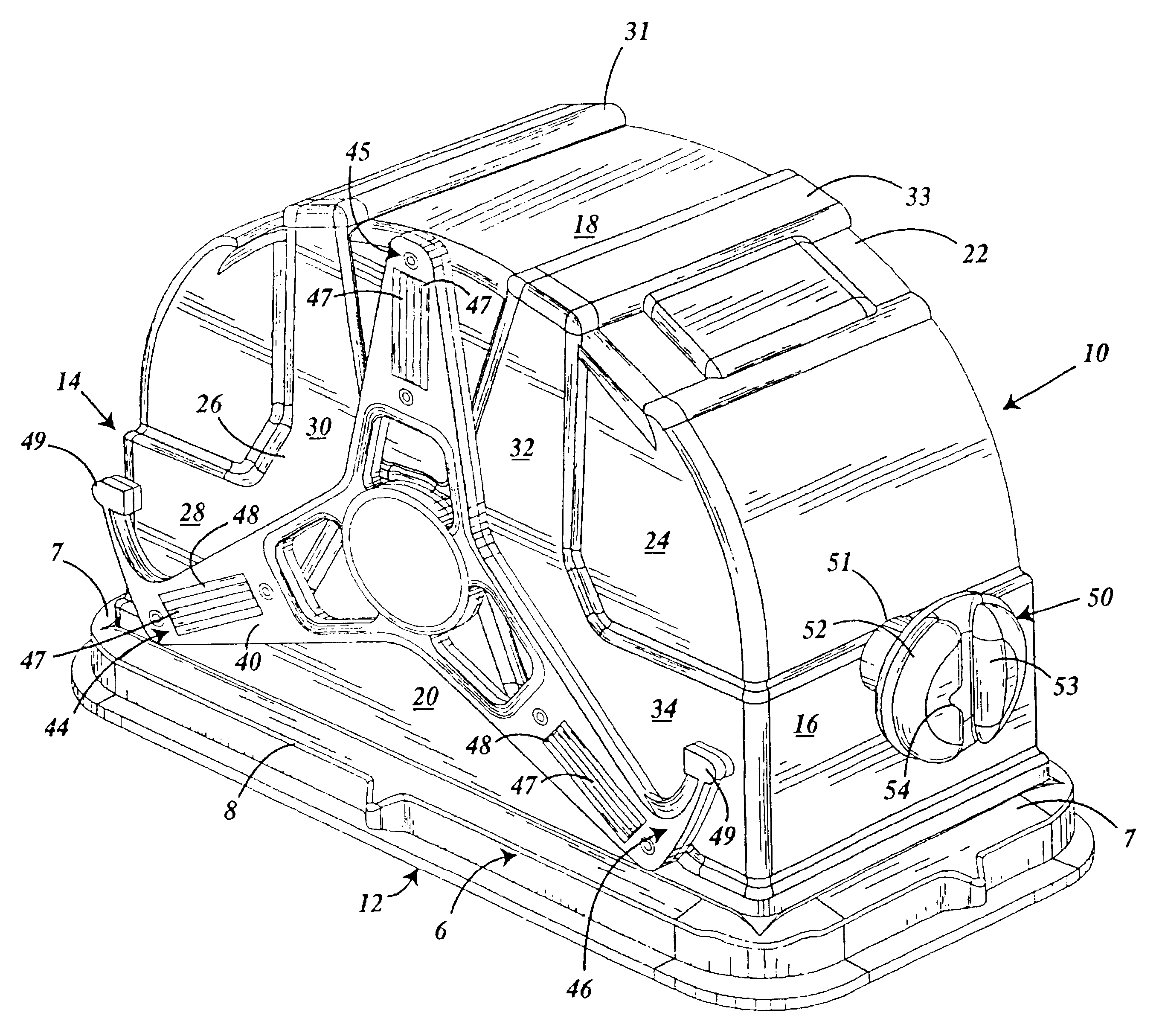
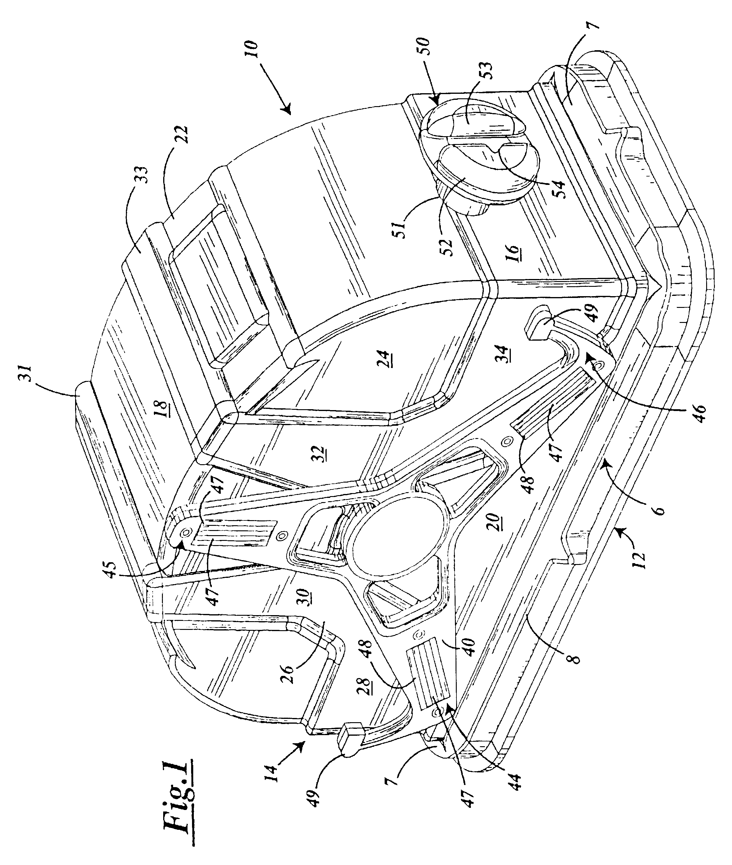
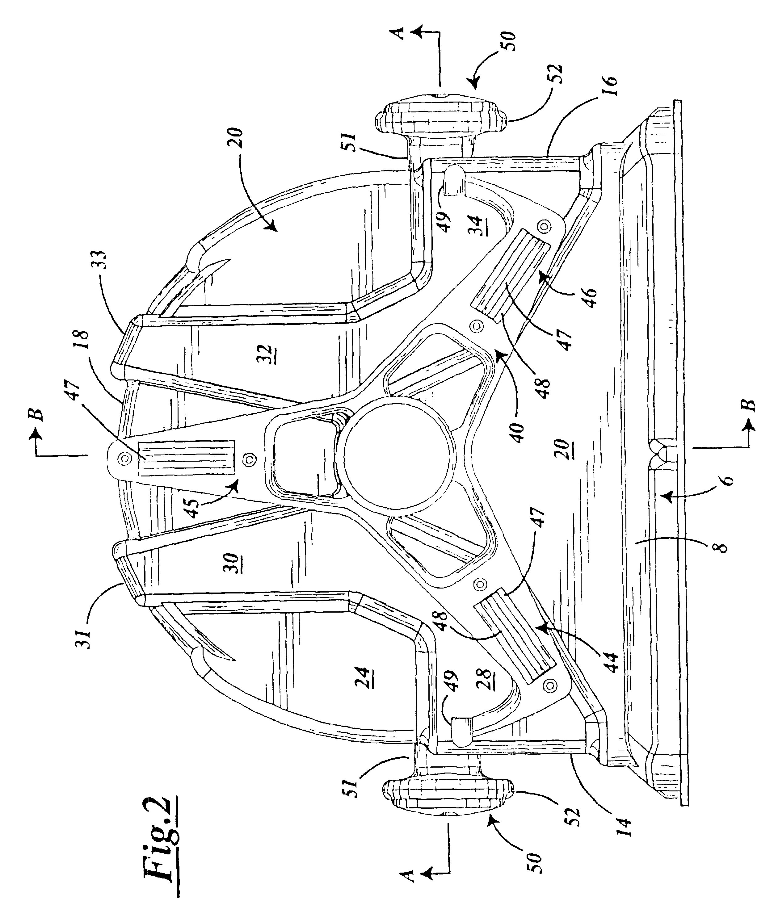
As shown in FIG. 1, the container of the present invention has an exterior shell 10. The exterior shell 10 has six sides 12, 14, 16, 18, 20 and 22.

Side 12 comprises a door frame 6 having a pair of opposing end portions 7 and a pair of side portions 8. Sides 14 and 16 of the exterior shell 10 are defined generally by straight walls extending from the opposite end portions 7 of the door frame 6. Wall 18 extends between walls 14 and 16 and is in the shape of a partial cylinder. The radius of curvature of wall 18 is generally the same as the radius of curvature of the wafer to be stored in the container. Top and bottom walls 20 and 22 complete the shell. Walls 20 and 22 have a generally flat surface 24 and a reinforcement member 26 projecting outwardly from the flat surface 24. Reinforcement member 26 prevents warpage of the container and especially walls 20 and 22. Reinforcement members 26 have four legs 28, 30, 32 and 34. Extending across wall 18 between the two legs 30 is a cross-bra...


PUM


Abstract

A container for creating a microenvironment is disclosed. The container includes a shell, a door and a plurality of supports having a unique design which are used to securely retain items, such as silicon wafers, in a spaced apart parallel relationship. The supports are removable. An electrical path is provided to ground the supports. Kinematic coupling structures are also provided for positioning the container on a surface so as to, for example, properly align the door with the port of a wafer processing tool.

Description

BACKGROUND OF THE INVENTIONI. Field of the InventionThe present invention relates generally to a package for an item. More particularly, the present invention relates to a package specifically designed to isolate from contamination materials used in the manufacture of electronic semiconductor components and circuits. Such packages are particularly well suited for substrates, wafers, memory disks, photomasks, flat panel displays, liquid crystal displays, and the like.II. Description of the Prior ArtVarious containers have been used for centuries to transport items from one place to another. Such containers have, for example, been used to provide a way to confine items in a space for efficient storage. Such containers also provide an easy way of handling items. Another important function provided by packages and containers is protection.Substrates used in the manufacture of semiconductor circuits, rigid memory disks, photomasks, liquid crystal displays, and flat panel displays can be ...

Claims


Application Information

Patent Timeline
IPC IPC(8): H01L21/67H01L21/673H01L21/677B65D85/48B65DG11B33/04G11B33/14
CPCG11B33/0405G11B33/14H01L21/67369H01L21/67379H01L21/67383H01L21/67396H01L21/67763B65D85/48
Inventor GREGERSON, BARRYGALLAGHER, GARYWISEMAN, BRIAN
Owner ENTEGRIS INC
Learn More