Spinal fixation apparatus and method

a technology of fixation apparatus and spine, which is applied in the field of medical instruments, can solve the problems of increased degenerative change rate, traumatic injury, and excessive force on the spine, and achieve the effects of reducing the risk of traumatic injury, facilitating implantation, and being easy to manipula

Inactive Publication Date: 2006-10-03
BRYAN DONALD W
View PDF24 Cites 54 Cited by
  • Summary
  • Abstract
  • Description
  • Claims
  • Application Information

AI Technical Summary

Benefits of technology

[0016]This invention relates to a novel spinal fixation apparatus and method and includes specially designed C-clamps, cross-link plates, stem clamps, bone screws, and longitudinal rods—all of which are used for spinal fixation. The various components are designed to be interchangeable, highly adaptable, and easily manipulated by the surgeon at time of implantation. The bone screws provide greater gripping strength and ease of implantation.
[0019]Another object of this invention is to provide a spinal fixation apparatus that has interchangeable components, is greatly simplified, and has infinite capability to locate bone screws in any orientation without the necessity of bending the longitudinal rods thereby also allowing the use of more biocompatible materials, such as titanium, which exhibits less image interference (scatter) on a CT scan.
[0021]Another object of this invention is to provide a cross-link plate with a squared cross-section at its midriff to allow the cross-link plate to be bent or twisted to adapt to specific anatomy and increase ease and accuracy of implantation.
[0024]Another object of this invention is to provide a bone screw that can be positioned prior to tightening without creating undue coaxial forces on the cancellous bone tissue.
[0025]Another object of this invention is to provide a bone screw thread configuration that supplies greater gripping strength due to the top surface of the thread being nearly orthogonal relative to the axis of the bone screw.

Problems solved by technology

In fulfilling its role in the back, the spine can be subjected to significant trauma which is assumed to play a dominant role in the etiology of low back pain, Trauma frequently results in damage at the upper end of the lumbar spine, where the mobile lumbar segments joint the less mobile dorsal spine.
Excessive forces on the spine can not only produce life-threatening traumatic injuries, but may contribute to an increased rate of degenerative change.
Severe scoliosis that goes untreated can cause deformities of the ribs that restrict the lung and later cause serious breathing problems, heart disease, or severe back pain.
Internal spinal fixation increases rigidity and results in a high rate of fusion.
However, the pseudarthrosis rate for this procedure was unacceptably high.
Most of these devices are relatively difficult to adjust and require undue surgical time in their implantation.
Further, due to the wide variation in spinal dimensions and availability of suitable attachment sites, most devices have limited application.
Further still, these devices do not allow the surgeon to easily manipulate and position the bone screws prior to final tightening of the device.
Generally, prior bone screw thread configurations have been either single thread pitch (number of threads per unit of length) over the entire length of the bone screw, which requires that the clamping device be engaged from the beginning of the threading process, or other complex configurations involving set screws, or other devices which are either cumbersome to adjust and tighten or cause undue disruption of the cancellous bone tissue.
Bone screws of differing thread pitch have an advantage that final positioning is not required until just prior to final tightening of the device, but still have the disadvantage of, due to the discrepancy in the thread pitch, causing the bone screw to create undue coaxial pressure on the lattice-like cancellous tissue of the bone, thereby increasing possible shearing or undue disruption of bone tissue.
A further characteristic of prior bone screw configurations is that the thread angle of the top surface of the thread is not orthogonal relative to the axis of the screw, thereby lessening gripping strength.

Method used


Image

  • Spinal fixation apparatus and method
  • Spinal fixation apparatus and method
  • Spinal fixation apparatus and method

Examples


Embodiment Construction

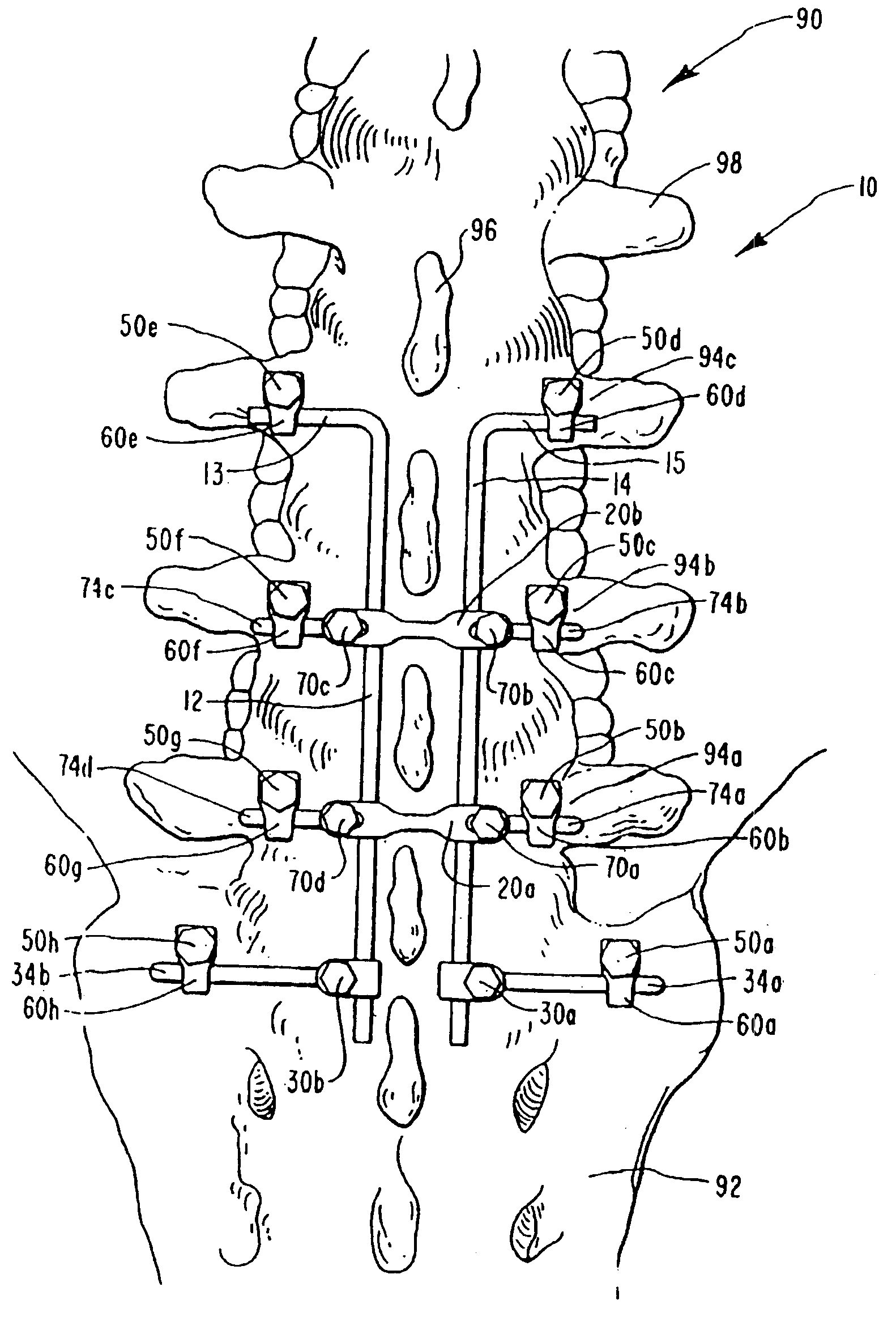
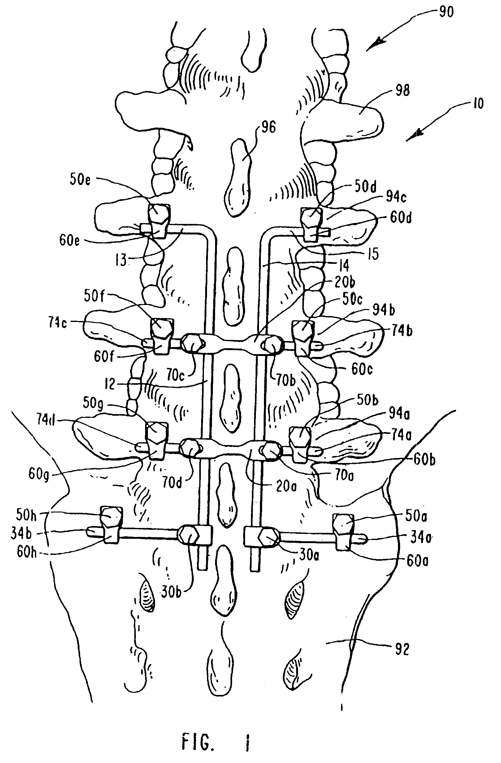
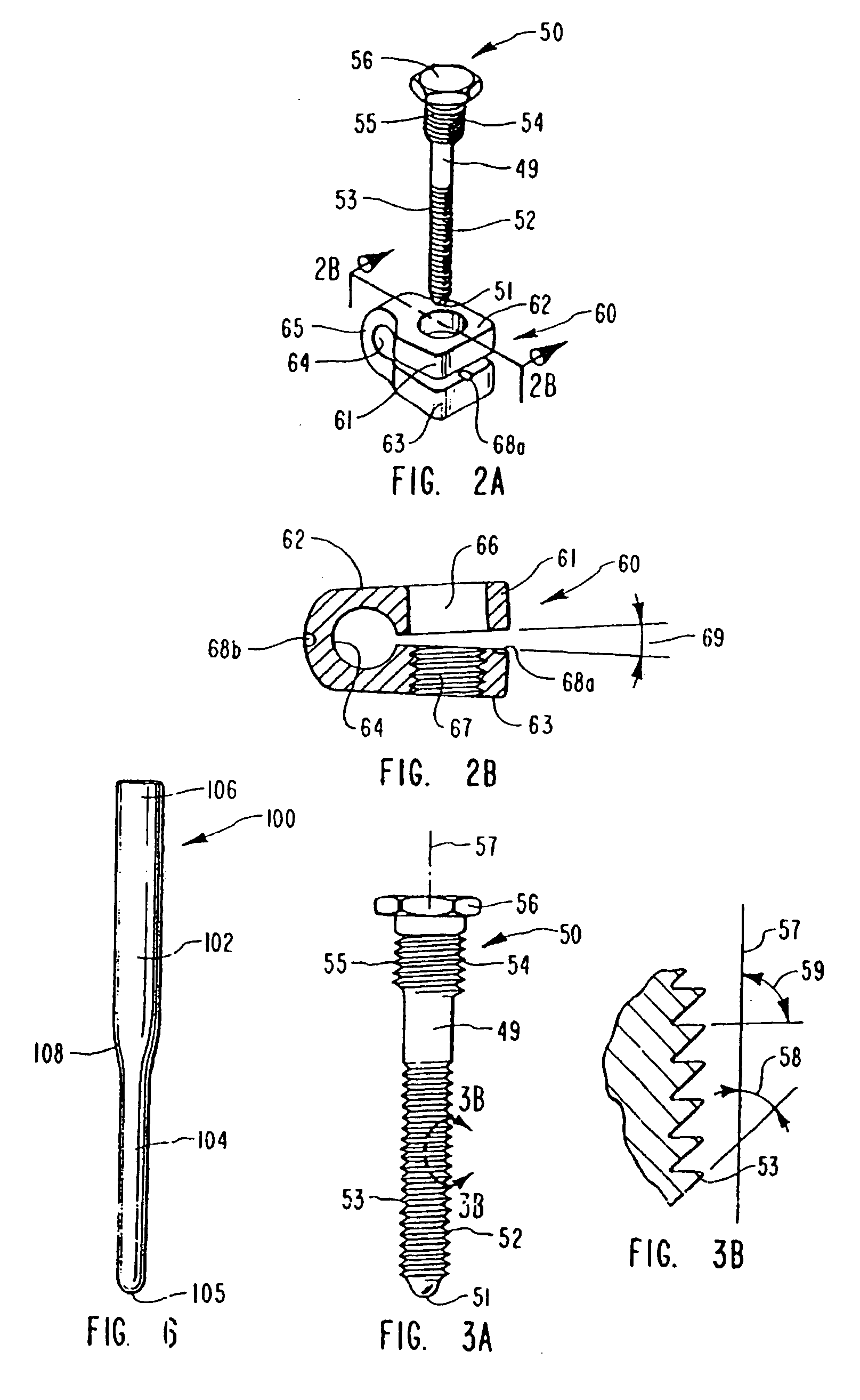
[0037]The invention is best understood from the following description with reference to the drawing wherein like parts are designated by like numerals throughout and taken in conjunction with the appended claims.

General Discussion

[0038]The underlying rationale for spinal fusion is to (a) restore the integrity of the spine or to replace missing bone stock, i.e., fracture, tumor, infection; (b) produce an arthrodesis that will suppress undesired movement between two or more bony elements that are the source of pain; and (c) maintain correction of spinal deformity or to prevent progression of deformity. In general, this arthrodesis is produced by using a bone graft that will heal and mature thereby binding the involved elements intimately. Arthrodesis requires in most instances a period of immobilization to achieve this end. Importantly, the key factor in predicting successful fusion is the amount of instability; that is, if instability is moderate and bone stock good,the proportion of...


PUM


Abstract

A spine fixation apparatus and method including at least one longitudinal rod mounted parallel to the axis of the spine and having a plurality of stem clamps adjustably mounted to the longitudinal rod. Each stem clamp has a stem extending outwardly therefrom with the diameter of the stem being identical to the diameter of the longitudinal rod. A plurality of C-clamps are provided and are mounted to the stems and to the longitudinal rods. A plurality of bone pins are provided and are used to preliminarily mount the spinal fixation construct to the spine to allow the surgeon to determine by X-ray the accuracy of the construct with regard to the spine. A plurality of innovative bone screws are used to simultaneously anchor the C-clamps to the bone and to the respective stem and longitudinal rod. The bone screws are configured with a smaller diameter at the distal end having threads thereon for threadedly engaging the underlying bone. The bone screw includes a threaded shoulder for threadedly engaging the Cclamp to clamp the same to the stems and the longitudinal rod. The thread pitch is identical for both threaded sections of the bone screw. A second longitudinal rod can also be used to create the spinal implant construct and be coupled to the first longitudinal rod through a plurality of cross-link plates.

Description

RELATED APPLICATIONS[0001]This application is a continuation-in-part application of my application Ser. No. 08 / 232,371, filed Apr. 25, 1994, for SPINAL FIXATION APPARATUS AND METHOD now U.S. Pat. No. 5,498,262 issued Mar. 12, 1996, which was a continuation-in-part application of Ser. No. 07 / 999,005 filed Dec. 31, 1992 for LUMBAR SPINE FIXATION APPARATUS AND METHOD now U.S. Pat. No. 5,306,275 issued Apr. 26, 1994.BACKGROUND[0002]1. Field of the Invention[0003]This invention relates to medical instrumentation for achieving spinal fusion and, more particularly, to a novel, highly adaptive, and interchangeable component system and method for fixation of the lumbar spine and lumbosacral spine to aid the fusion of these spinal regions.[0004]2. The Prior Art[0005]The spine is a flexible, multi-segmented column that supports the upright posture in a human while providing mobility to the axial skeleton. The lumbar spine serves the functions of encasing and protecting vital neural elements an...

Claims


Application Information

Patent Timeline
Patent Type & Authority Patents(United States)
IPC IPC(8): A61B17/70A61B17/17A61B17/80A61B17/86A61B17/88
CPCA61B17/1757A61B17/7004A61B17/7007A61B17/7011A61B17/7038A61B17/7041A61B17/7044A61B17/7049A61B17/7055A61B17/7062A61B17/7067A61B17/86
Inventor BRYAN, DONALD W.
Owner BRYAN DONALD W
Why Eureka
Try Eureka