

Lens with variable focus
a technology of variable focus and lens, applied in the field of variable focal lens, can solve the problems of difficult manufacturing or inefficiency of the system, insufficient prior art system for forming variable lens, etc., and achieve the effect of simple manufacturing and simple us
- Summary
- Abstract
- Description
- Claims
- Application Information
AI Technical Summary
Benefits of technology
Problems solved by technology
Method used
Image


Examples
first embodiment
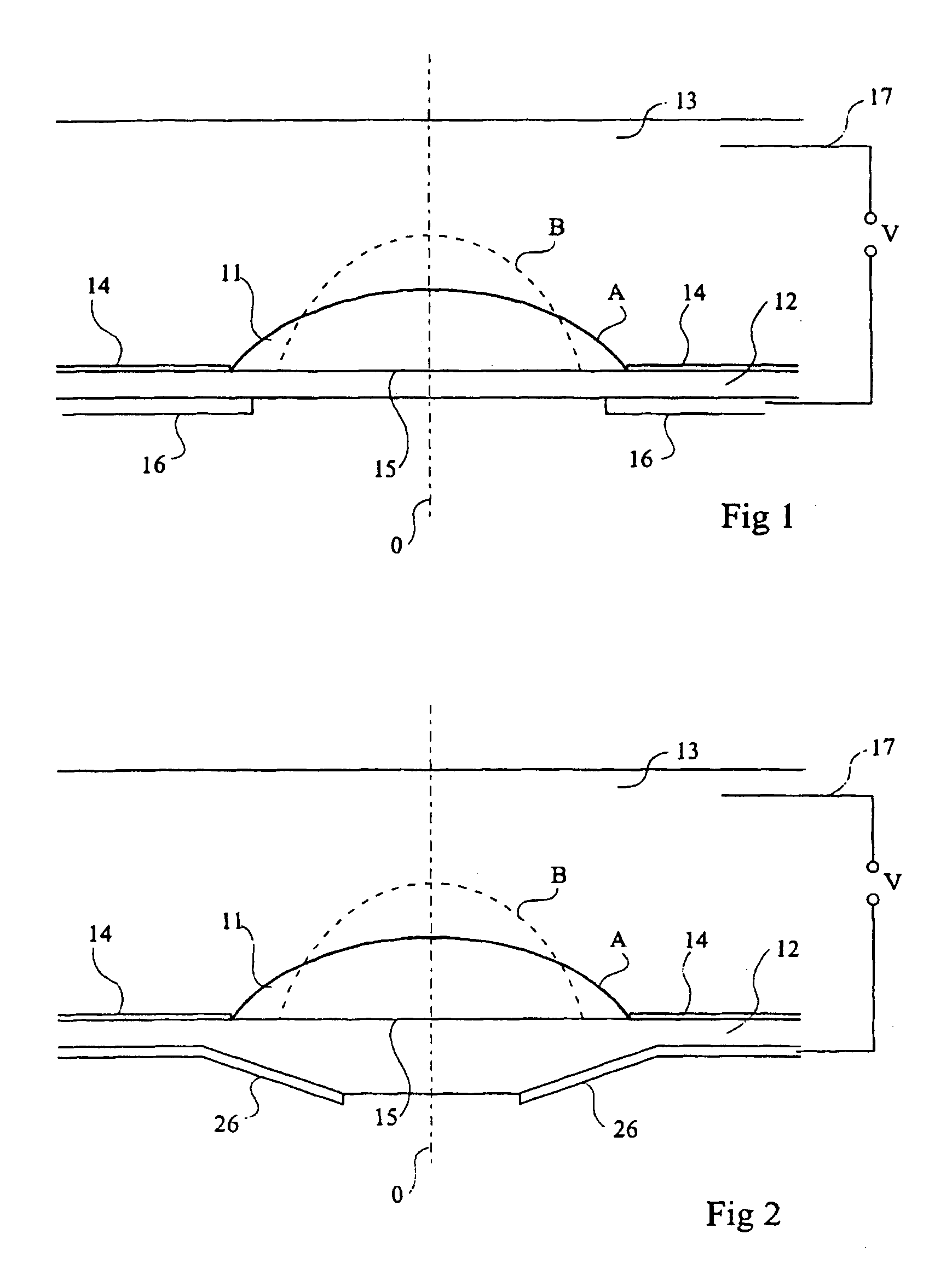
[0028]FIG. 1 shows a simplified cross-section view of a variable focus liquid lens according to the present invention. A drop of an insulating liquid 11 is located on the internal surface of a wall of a dielectric chamber 12 filled with a conductor liquid 13. The insulating liquid 11 and the conductor liquid 13 are both transparent, not miscible, have different optical indexes and have substantially the same density. The dielectric 12 naturally has a low wetting with respect to the conductor liquid 13. A surface treatment 14 insuring a high wetting of the wall of the dielectric chamber with respect to the conductor liquid 13 surrounds the contact region 15 between the insulating liquid drop 11 and the wall of chamber 12. The surface treatment 14 maintains the positioning of drop 11, preventing the insulating liquid from spreading beyond the desired contact surface. When the system is at rest, the insulating liquid drop 11 naturally takes the shape designated by reference A. “O” desi...
third embodiment
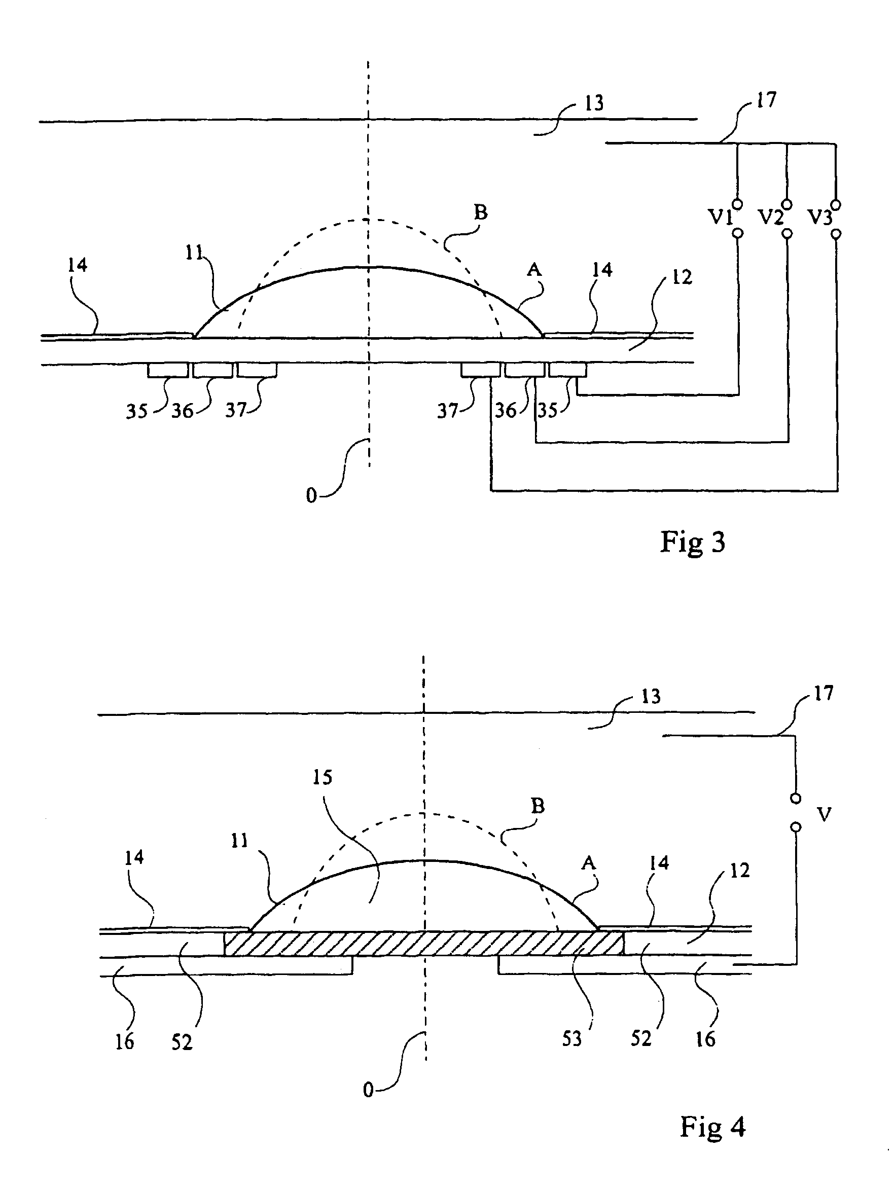
[0034]FIG. 3 shows a simplified cross-section view of a variable focus liquid lens according to the present invention. Elements such as drop 11, axis O, chamber 12, conductor liquid 13, surface treatment 14, contact region 15 and electrode 17 are the same as those of the embodiment described in FIG. 1. The positions A and B also correspond to the rest position of drop 11 and to the limit position of drop 11, respectively.
[0035]In this third embodiment, on the external surface of the wall of chamber 12 is placed a group of three circular concentric electrodes, 35, 36 and 37, insulated from each other, and having O as axis. A voltage may be applied between each of electrodes 35, 36 and 37 and electrode 17; exemplary voltages V1, V2 and V3 are shown, each of which may vary. The voltages are chosen at any time with decreasing values towards axis O so that the electric field generated by applying the voltages to electrodes 35, 36 and 37 decreases radially towards the center of region 15....
fourth embodiment
[0037]FIG. 4 shows a simplified cross-section view of a variable focus liquid lens according to the present invention. Elements such as drop 11, axis O, conductor liquid 13, surface treatment 14, contact region 15 and electrodes 16 and 17 are the same as those of the embodiment described in FIG. 1. The positions A and B also correspond to the rest position of drop 11 and to the limit position of drop 11, respectively.
[0038]In this fourth embodiment, the wall of the dielectric chamber 52 on which the insulating liquid drop 11 is placed, comprises a circular dielectric region 53, letting through the light about axis O. Region 53 has a low wetting with respect to conductor liquid 13 in the absence of a surface treatment 14. Region 53 has been treated in such a way that its dielectric constant varies radially and continuously towards axis O, and that the electric field generated by voltage V has a gradient which decreases radially towards axis O on the contact region 15. When voltage V ...
PUM
| Property | Measurement | Unit |
|---|---|---|
| diameter | aaaaa | aaaaa |
| frequency | aaaaa | aaaaa |
| frequency | aaaaa | aaaaa |
Abstract
Description
Claims
Application Information