Computer controlled hydraulic resistance device for a prosthesis and other apparatus

a computer controlled and hydraulic resistance technology, applied in the field of computer controlled hydraulic resistance devices for prostheses and other apparatuses, can solve the problems of amputees walking with a slightly unnatural gait, mechanical braking mechanisms that are difficult to keep adjusted properly, and it is not feasible to duplicate muscle contraction, etc., to achieve high resistance, slow the prosthesis, and the effect of high resistan

Inactive Publication Date: 2007-12-25
OSSUR HF
View PDF97 Cites 77 Cited by
  • Summary
  • Abstract
  • Description
  • Claims
  • Application Information

AI Technical Summary

Benefits of technology

[0013]The valve used in one embodiment of the device is a proportional controlled, solenoid actuated, balanced spool valve. The shape of the spool is such that flow across the face of the spool has little or no effect on spool movement, thus eliminating any possibility of unbalanced flow induced forces. The valve spool is also pressure balanced to eliminate any possibility of a hydraulic lock. The magnetic core for the valve is shaped to produce a near constant force in the working stroke of the spool when constant power is supplied. In another embodiment, a two stage poppet or pilot operated valve is used to increase the servo valve dynamic range and to reduce significantly the unbalanced forces applied. Valve control includes a high frequency dithering to avoid spool drag, and proportional control is provided to minimize wear rate as normally associated with a pulse width modulated control.
[0019]Constants in the state equations are able to adapt with changes in the system operating environment. If the difference between the actual and required pressure differential is large, the microprocessor changes the valve in large increments to compensate for this large error. If the difference between the actual and required pressure differential is small, the microprocessor changes the valve in smaller increments to compensate for this small error. If the knee angle is extending and nearing full extension, the microprocessor starts to close the valve to create a high resistance and slow the prosthesis in the extension direction. When the knee angle is flexing and nearing the ideal heel rise, the microprocessor starts to close the valve to create a high resistance and slow the prosthesis in the flexion direction. The prosthetic measured force allows the microprocessor to distinguish between heel strike, mid-stance, or toe off. This aids the amputee in descending stairs by creating a high knee resistance and lowering the amputee to the next stair by using his own weight.

Problems solved by technology

It has not been feasible to duplicate muscle contraction in leg prosthesis because of the weight and bulk that would be required to duplicate this function.
Mechanical braking mechanisms can be difficult to keep adjusted properly and can cause the amputee to walk with a slightly unnatural gait.
Position activated polycentric mechanisms require more concentration and can be difficult for amputees to use in some situations.

Method used


Image

  • Computer controlled hydraulic resistance device for a prosthesis and other apparatus
  • Computer controlled hydraulic resistance device for a prosthesis and other apparatus
  • Computer controlled hydraulic resistance device for a prosthesis and other apparatus

Examples


Embodiment Construction

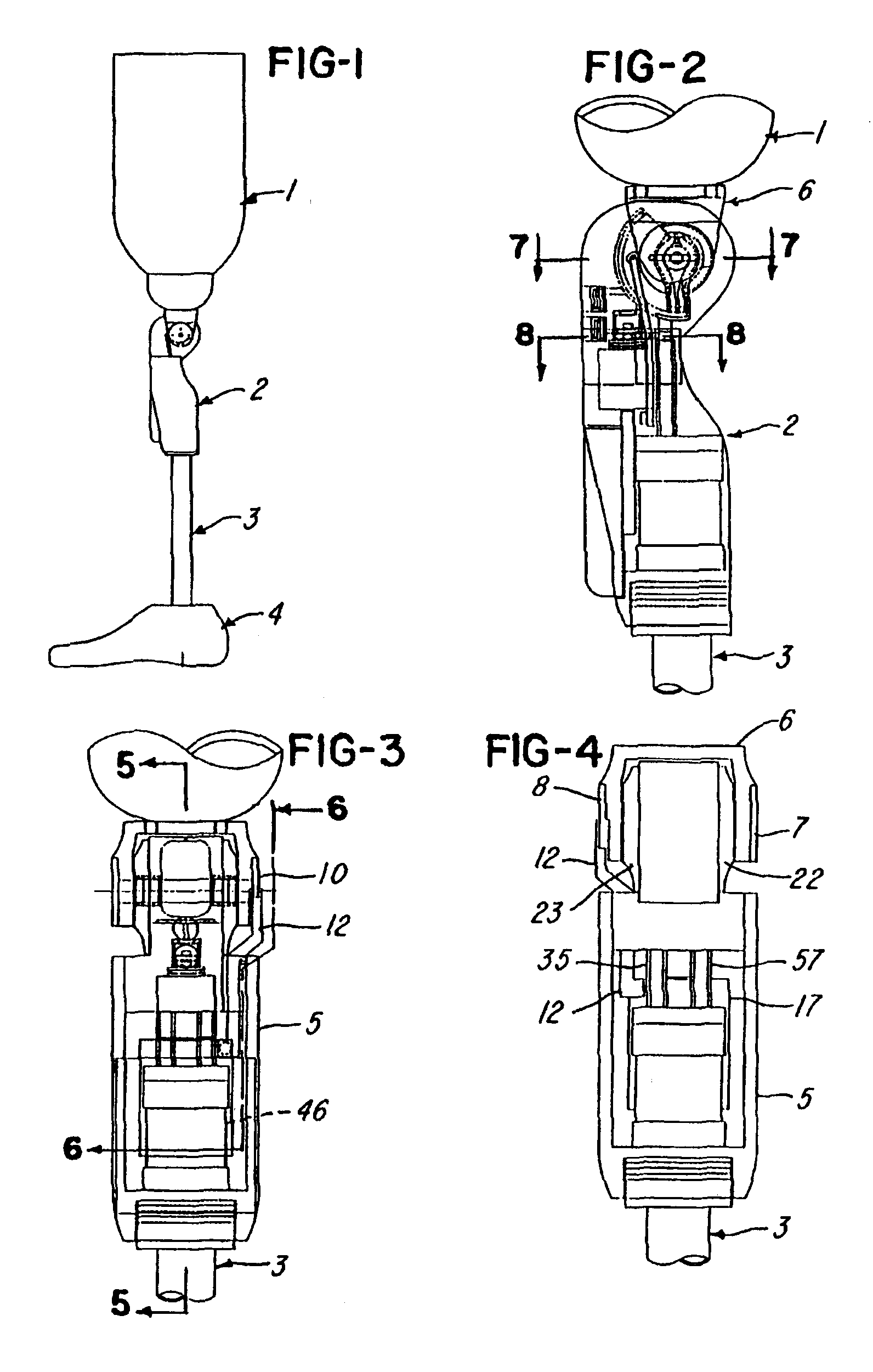
[0055]In reference to FIG. 1, a typical lower limb prosthesis for an above-knee amputee includes a residual limb socket 1 which functions as an interface between the amputee and the prosthesis, a knee control assembly or unit 2 which provides knee rotation and resistance to aid in walking, a mounting pylon 3 and a foot 4. The components 1, 3 and 4 are conventional and commercially available.

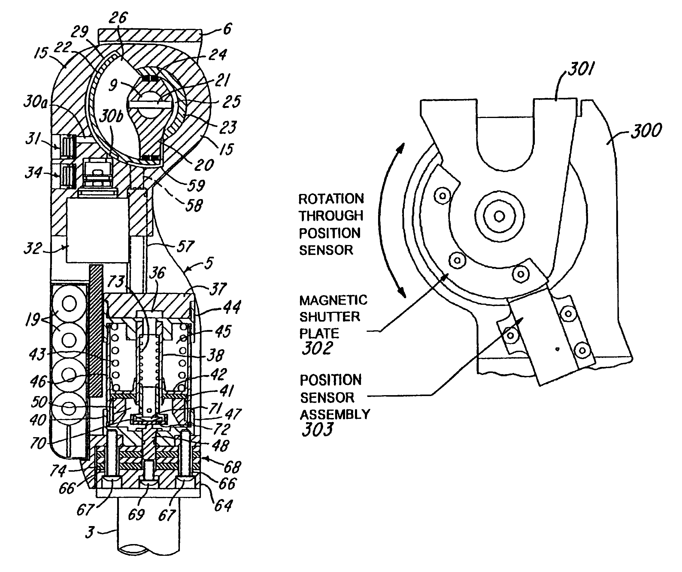
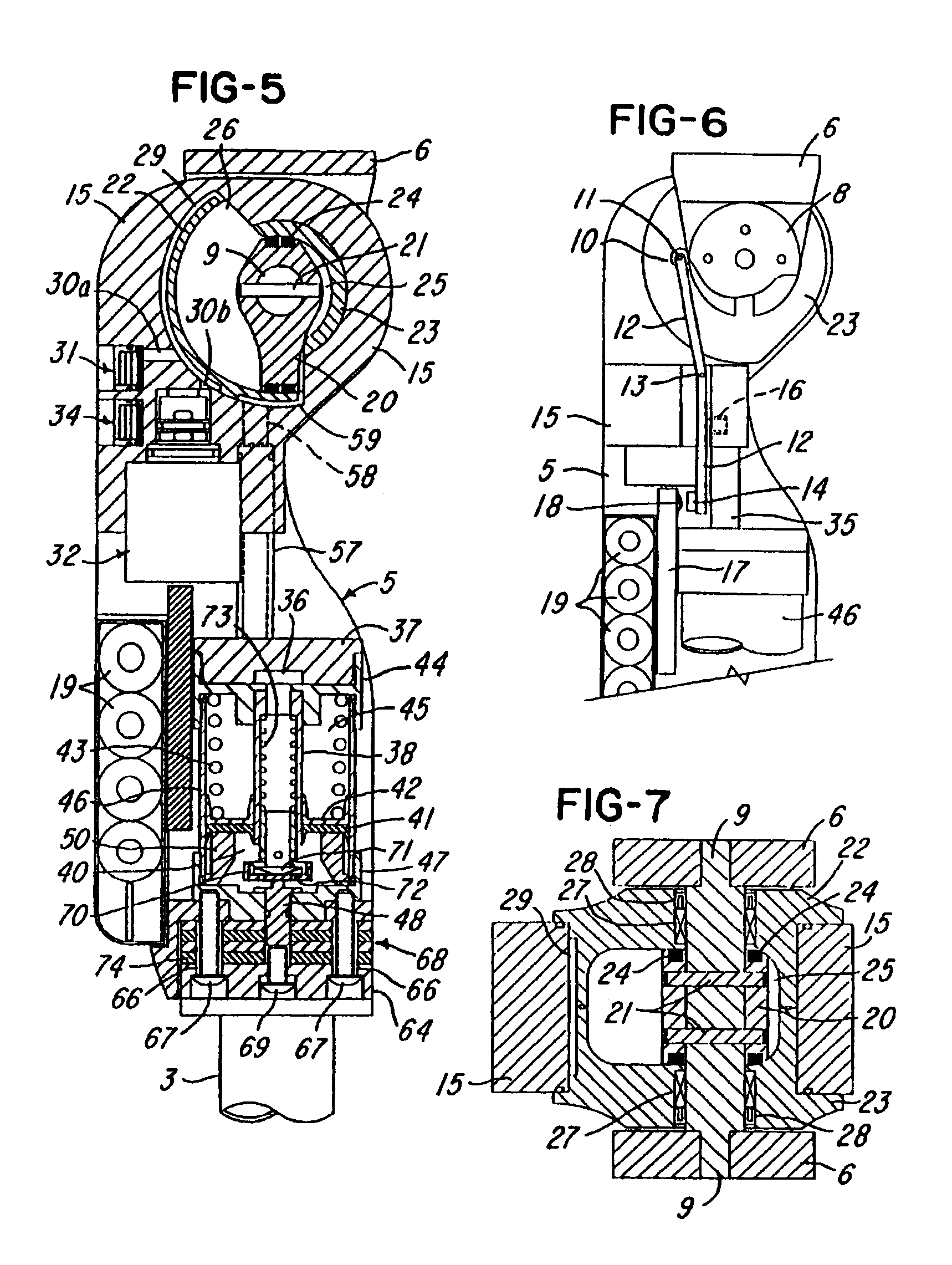
[0056]The knee control assembly or unit 2 is described in connection with FIGS. 2-14 and includes a frame assembly 5 and an inverted U-shaped knee bracket 6 secured to the socket 1. The knee bracket 6 includes a right side retainer plate 7 and a left side retainer plate 8. The knee bracket 6 slides over opposite end portions of a rotor shaft 9 (FIG. 5), and each end portion has parallel flats to key the shaft to the bracket. The side retainer plates 7 and 8 are secured to the bracket 6 by screws, and the shaft 9 rotates with the knee bracket 6 relative to the frame 5. The left side retainer plate...


PUM


Abstract

A computer controlled hydraulic resistance device for apparatus such as a prosthetic knee for above knee amputees, includes a two stage pilot operated solenoid valve connected to control the flow of hydraulic fluid to and from a hydraulic actuator which applies resistance to the prosthetic knee or other apparatus through a coupling. Hydraulic pressure is sensed on the high and low side of the actuator by a spring biased magnet and a magnetically actuated electronic sensor and is used by a micro-controller in a closed-loop manner to compensate automatically for variations in the device and in the hydraulic fluid viscosity. The device also has magnetically actuated electronic sensors which sense positions of the apparatus and feed back to the micro-controller for applying a predetermined resistance profile to the apparatus.

Description

RELATED APPLICATION[0001]This application is a continuation-in-part of application Ser. No. 08 / 883,614, Filed Jun. 26, 1997, now U.S. Pat. No. 5,888,212. This application also claims the benefit of prior application Ser. No. 60 / 020,904, Filed Jun. 27, 1996.<?delete-end id="DEL-S-00001" ?> <?insert-start id="INS-S-00001" date="20071225" ?>This application is a continuation of application 10 / 237,571, filed 5 Sep. 2002 (abandoned), which is a reissue of U.S. Pat. No. 6,113,642, issued 5 Sep. 2000, which is a continuation-in-part of application 08 / 883,614, filed 26 Jun. 1997(now U.S. Pat. No. 5,888,212), which claims the benefit of provisional application 60 / 020,904, filed 27 Jun. 1996.<?insert-end id="INS-S-00001" ?>BACKGROUND OF THE INVENTION[0002]The present invention is ideally suited for use with an artificial leg or prosthesis worn by an above knee amputee, but also has other applications and uses. Normally this type of prosthesis involves an artificial knee jo...

Claims


Application Information

Patent Timeline
Patent Type & Authority Patents(United States)
IPC IPC(8): A61F2/64A61F2/60A61F2/70A61F2/74A61F2/76A61F2/50A61F2/68F16F9/44F16F9/46
CPCA61F2/64A61F2/70A61F2002/5006A61F2002/5007A61F2002/5032A61F2002/5072A61F2002/704A61F2002/7625A61F2002/7635A61F2002/7655A61F2/74A61F2/748F16F9/46F16F9/464
Inventor PETROFSKY, STEVEN H.GRUESBECK, WILLIAM G.
Owner OSSUR HF
Why Eureka
Try Eureka