Image pickup lens system

Inactive Publication Date: 2009-02-17
ENPLAS CORP
View PDF3 Cites 10 Cited by
  • Summary
  • Abstract
  • Description
  • Claims
  • Application Information

AI Technical Summary

Benefits of technology

[0018]Accordingly, it is an object of the present invention to provide an image pickup lens system, wherein even when the image pickup elemen

Problems solved by technology

First of all, in the image pickup element such as CCD, CMOS and the like, 100% of light obliquely entering into the image pickup element cannot be utilized for the structural reason, unlike a silver-salt film and hence, it is required that light enters into a lens at an angle closer to the vertical at any position on the image pickup element. In other words, it is required that a telecentric property is high, and a distance between the image pickup element and a pupil is large.
Therefore, the following problem is encountered: It is extremely difficult that the image pickup lens used in the conventional ¼ inch sensor is reduced in size and used for th

Method used


Image

  • Image pickup lens system
  • Image pickup lens system
  • Image pickup lens system

Examples


example 1

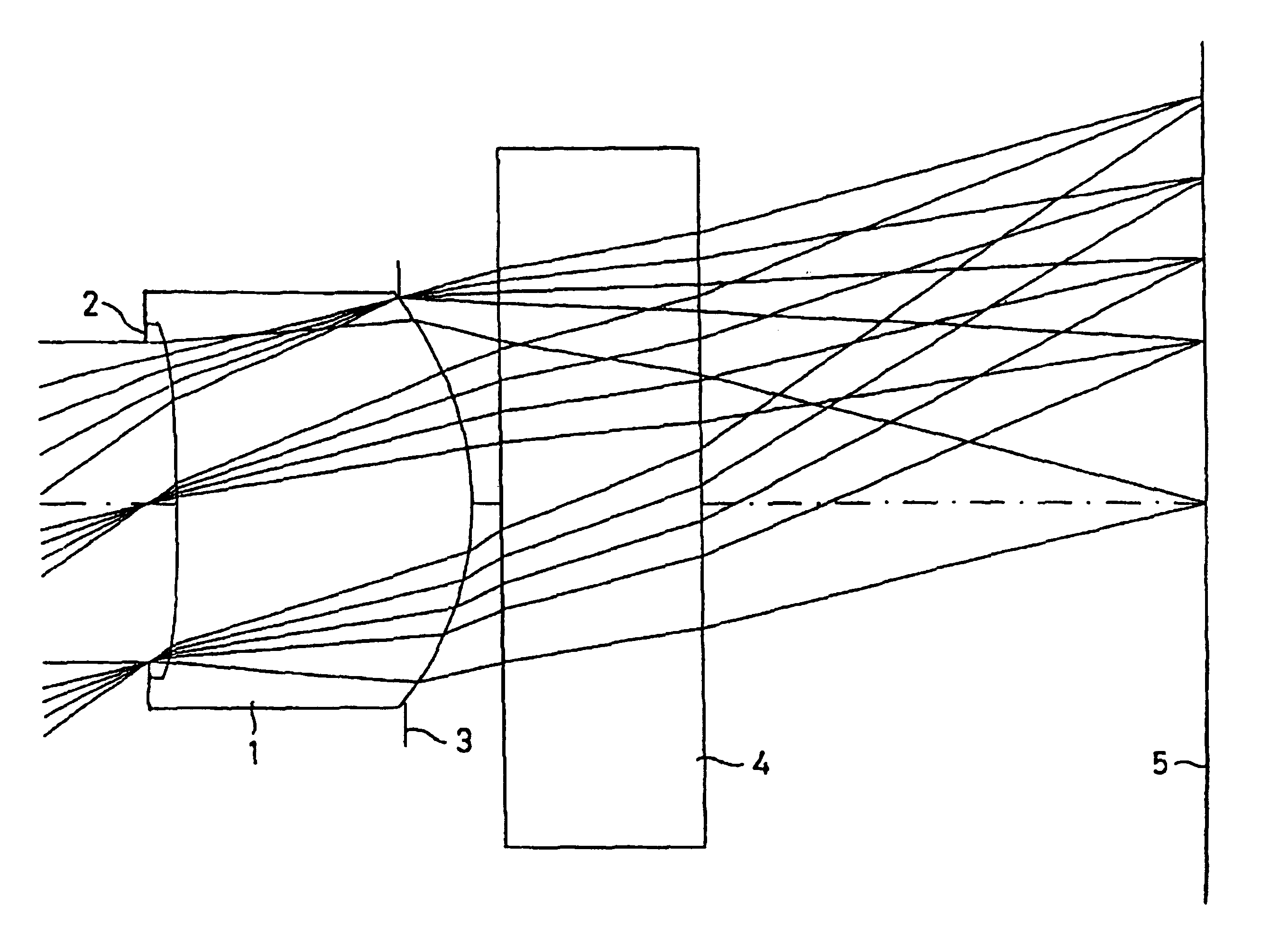
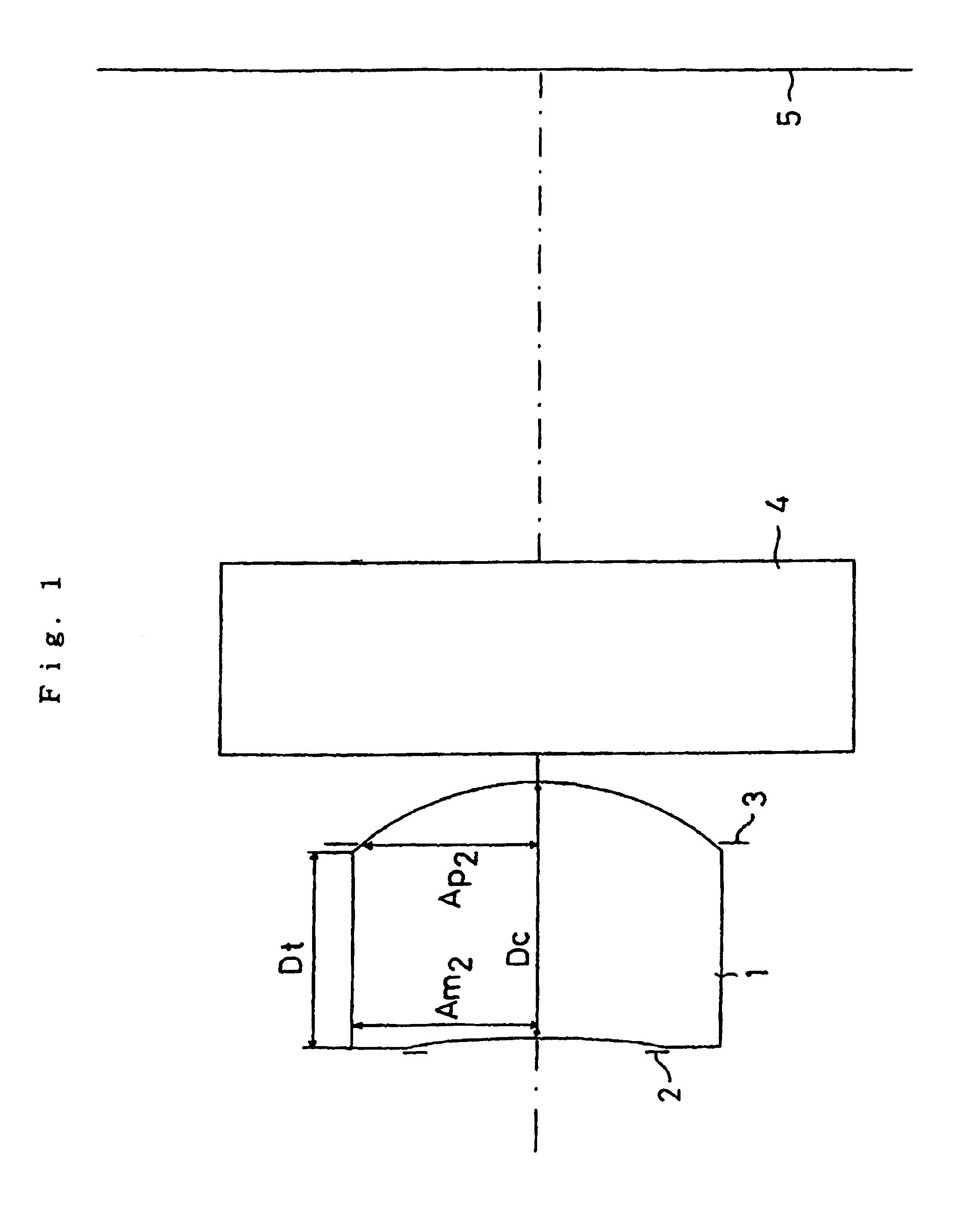
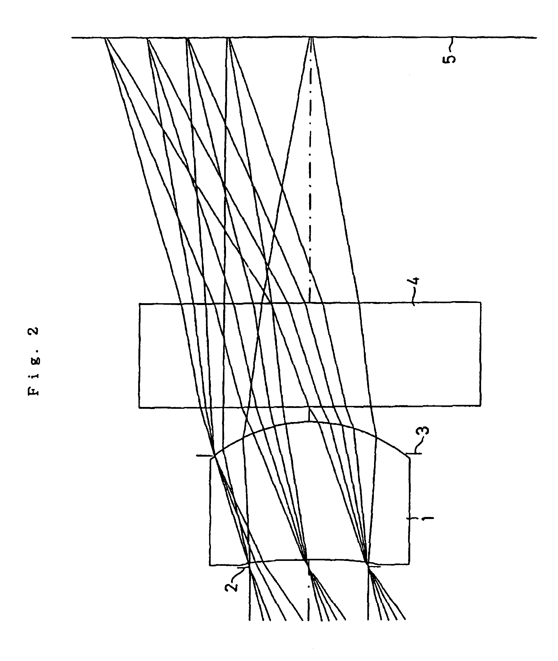
[0060]FIG. 2 shows a first example of the present invention. This example is an image pickup lens system having an arrangement shown in FIG. 1. The image pickup lens system in this example is set under the following conditions:[0061]F=2.8; fl=2.19 mm; Y′=1.35 mm; Dc=0.90 mm; Dt=0.70 mm; Am2=0.65 mm; Ap2=0.62 mm; S=0.05 mm; and r2=0.99 mm.

[0062]

RadiusRefractiveAbbe constantFacer of curvatureDistance dindex ndνd(1) Diaphragm0.0000.0500(2) First face−5.1530.90001.5256.0of lens(3) Second face−0.9890.0000of lens(4) First face0.0000.70001.5264.2of cover glass(5) Second face0.0001.8597of cover glass(6) CCD faceKAB23.450423e + 001−3.596798e − 001  1.975480e + 00031.339285e − 001  5.011488e − 002−5.827157e − 002c2−8.831343e + 0003  7.319106e − 003

[0063]Under such conditions, Y′ / fl=1.35 / 2.19=0.616 is established to meet the expression (1).

[0064]In addition, Dt / Dc=0.70 / 0.90=0.78 is established to meet the expression (2).

[0065]Further, Ap2 / Am2=0.62 / 0.65=0.95 is established to meet the expressio...

example 2

[0071]FIG. 4 shows a second example of the present invention. The image pickup lens system is set under the following conditions:[0072]F=2.0; fl=1.67 mm; Y′=1.05 mm; Dc=0.85 mm; Dt=0.75 mm; Am2=0.55 mm; Ap2=0.50 mm; S=0.10 mm; and r2=0.85 mm.

[0073]

RadiusRefractiveAbbe constantFacer of curvatureDistance dindex ndνd(1) Diaphragm0.0000.1000(2) First face−30.9710.85001.5256.0of lens(3) Second face−0.8510.0000of lens(4) First face0.0000.70001.5264.2of cover glass(5) Second face0.0001.2213of cover glass(6) CCD faceKaB2  0.000000e + 000−4.680585e − 001  7.754132e − 0013−1.339285e − 001−1.199533e − 001−1.180505e − 001C2−5.542358e + 0003−4.081729e − 003

[0074]Under such conditions, Y′ / fl=1.05 / 1.67=0.629 is established to meet the expression (1).

[0075]In addition, Dt / Dc=0.75 / 0.85=0.88 is established to meet the expression (2).

[0076]Further, Ap2 / Am2=0.50 / 0.55=0.91 is established to meet the expression (3).

[0077]Yet further, S=0.10 is established to meet the expression (4).

[0078]Yet further, |r2...

example 3

[0082]FIG. 6 shows a third example of the present invention. The image pickup lens system is set under the following conditions:[0083]F=2.0; fl=2.20 mm; Y′=1.35 mm; Dc=1.00 mm; Dt=0.84 mm; Am2=0.70 mm; Ap2=0.68 mm; S=0.10 mm; and r2=1.07 mm.

[0084]

RadiusRefractiveAbbe constantFacer of curvatureDistance dindex ndνd(1) Diaphragm0.0000.1000(2) First face−10.9501.00001.5256.0of lens(3) Second face−1.0680.0000of lens(4) First face0.0000.70001.5264.2of cover glass(5) Second face0.0001.8054of cover glass(6) CCD faceKAB20.000000e + 000−2.586316e − 0013.667821e − 00132.268728e − 001  4.688898e − 0022.073563e − 002C2−1.422459e + 0003  0.000000e + 000

[0085]Under such conditions, Y′ / fl=1.35 / 2.20=0.614 is established to meet the expression (1).

[0086]In addition, Dt / Dc=0.84 / 1.00=0.84 is established to meet the expression (2).

[0087]Further, Ap2 / Am2=0.68 / 0.70=0.97 is established to meet the expression (3).

[0088]Yet further, S=0.10 is established to meet the expression (4).

[0089]Yet further, |r2 / fl|=...


PUM


Abstract

An image pickup lens system includes a lens 1 of a meniscus shape having a first face as a convexconcave face, and a diaphragm 2 disposed on an object side of the lens 1. The lens 1 meets the following conditions: Y′/fl equal to or larger than 0.6; Dt/Dc is equal to or smaller than 0.9 and equal to or larger than 0.5; and Ap2/Am2 is equal to or larger than 0.9. Thus, even when an image pickup element is of a reduced size, a desired optical performance can be maintained, and it is possible to produce a lens easily with a back focal length ensured.

Description

BACKGROUND OF THE INVENTION[0001]1. Field of the Invention[0002]The present invention relates to an image pickup lens system and particularly, to an image pickup lens system of a single lens construction, which is used in an image pickup device (e.g., a CCD camera) utilizing an image pickup element such as CCD, CMOS and the like mounted in a mobile telephone or the like, and which can be reduced in weight and size.[0003]2. Description of the Related Art[0004]In recent years, the multimedia have been developed remarkably, and for example, the demand for a camera utilizing an image pickup element such as CCD, CMOS and the like adapted to be mounted in a portable computer, a visual telephone, a mobile telephone and the like, e.g., a CCD camera, is being increased remarkably. Such a CCD camera is required to be mounted in a limited space and for this reason, it is desired that the CCD camera is small in size and lightweight.[0005]Therefore, it is also desired that an image pickup lens s...

Claims


Application Information

Patent Timeline
IPC IPC(8): G02B13/18G02B13/04G02B3/00G02B9/02G02B13/00G02B13/22
CPCG02B3/04G02B9/02G02B13/0025G02B3/00
Inventor SAITO, TOMOHIRO
Owner ENPLAS CORP
Why Eureka
Try Eureka