Reduced-power GPS-based system for tracking multiple objects from a central location

a gps-based, low-power technology, applied in direction finders using radio waves, navigation instruments, instruments, etc., can solve the problems of inability to complete position determination, satellite and receiver clock synchronization leads to proportional range errors, and the range of receiver-satellite ranges cannot be estimated. , to achieve the effect of reducing energy

Inactive Publication Date: 2009-02-17
ASSET INTELLIGENCE
View PDF22 Cites 19 Cited by
  • Summary
  • Abstract
  • Description
  • Claims
  • Application Information

AI Technical Summary

Benefits of technology

[0025]Utilizing the present invention, power consumption and calculation complexity at the tracked object are reduced relative to that for a standard GPS receiver. Arrival time differences between satellite signals are measured at the tracked object and this information is relayed to the central station via the separate communications link. Satellite data streams need not be decoded at the tracked object.
[0026]The central station thereby necessarily determines the location of the object to be tracked. Because the receiver front end and data processor use significant power only when processing, the receiver power can be dramatically reduced by being “active” only long enough to get accurate time-difference measurements. This can be less than one second and requires no GPS data-frame synchronization because of the nature of the signals. For example, assuming that the tracked object is a railcar, new railcar locations typically are needed only as frequently as 15 minutes. Thus the receiver energy used is reduced in direct proportion to the reduction of “active” receiver time. Moreover, receiver complexity and cost can be reduced by replacing the advanced microprocessor employed in current GPS receivers with a simpler one that is matched to the arrival-time differencing tasks.
[0028]Another object is to provide a GPS-based asset tracking system which requires minimal energy at the tracked assets.

Problems solved by technology

With receiver noise and imperfect knowledge of satellite positions, the receiver-satellite ranges can only be estimated.
Any error in satellite and receiver clock synchronization leads to proportional range errors.
However, the full position determination is not made at the railcar.
This consumes significant power.

Method used


Image

  • Reduced-power GPS-based system for tracking multiple objects from a central location
  • Reduced-power GPS-based system for tracking multiple objects from a central location
  • Reduced-power GPS-based system for tracking multiple objects from a central location

Examples


Embodiment Construction

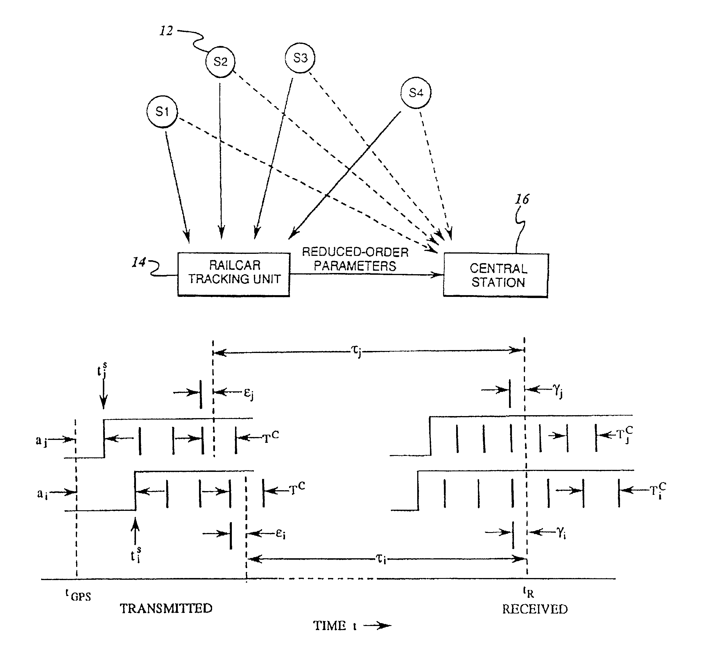
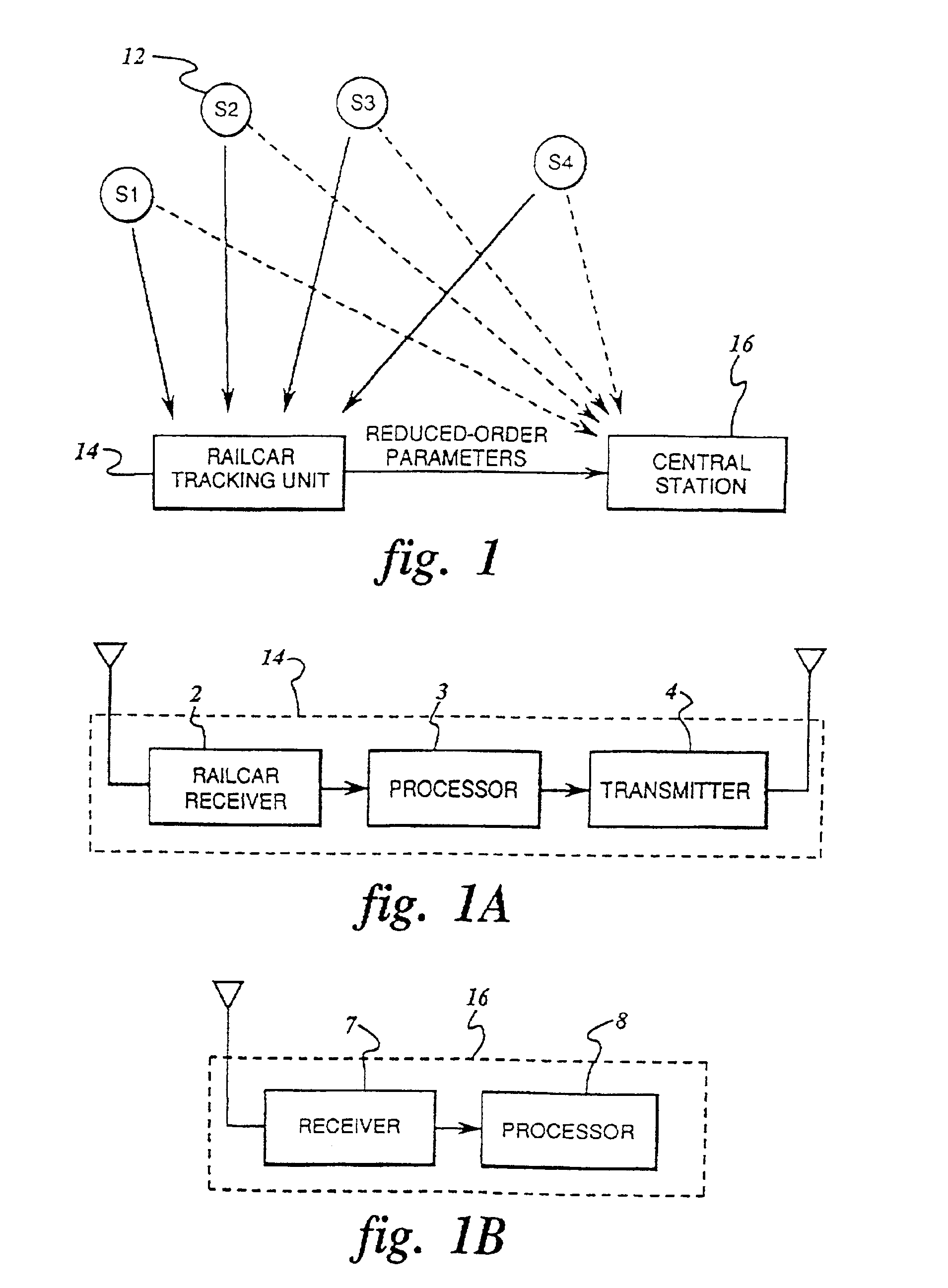
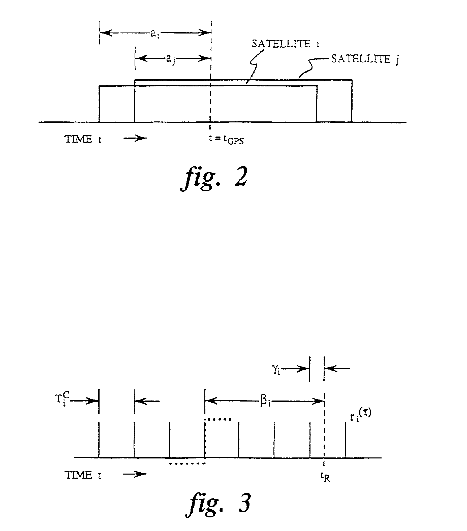
[0040]The present invention is directed to a system and method for reducing the power and complexity requirements of a local GPS receiver, which can be carried by a railcar, by effectively requiring only measurement of arrival-time differences between a plurality of GPS satellite signals. Data related to these time differences are transmitted to a central station where the majority of calculations required to determine the receiver (railcar) location are performed. In the preferred embodiments, a standard CDMA receiver is employed with radio frequency / intermediate frequency (RF / IF) front end and Gold-code cross correlators.

[0041]In FIG. 1, the invention is shown as comprising a plurality of GPS satellites 12, an object to be tracked, such as a railcar carrying a tracking unit 14, and a central station 16. Although the invention is herein described in the context of a railcar, the teachings of the invention are applicable to a variety of objects which may be tracked by a GPS or satel...


PUM


Abstract

Location of an object to be tracked is determined by measuring, at a receiver situated at the object, the propagation time differences between the signals from a plurality of GPS satellites, each of which is received by the receiver situated at the object. The measured propagation time difference values are transmitted to a central station where the location of the object to be tracked is calculated based upon the propagation time differences of the signals transmitted from the satellites and data derived from a receiver apart from the object but also receiving signals from the satellites.

Description

[0001]This application is a continuation of application Ser. No. 08 / 465,229 filed May 31, 1995 now abandoned.FIELD OF THE INVENTION[0002]This invention relates to object tracking systems used to locate and track multiple terrestrial (including water-based) objects and, more particularly, to power efficient object tracking systems based upon information obtained from satellites.BACKGROUND OF THE INVENTION[0003]The tracking and location of assets such as railcars, shipping or cargo containers, trucks, truck trailers, automobiles, etc. can be highly advantageous in commerce. Precise tracking of such vehicles and objects can facilitate their being allocated and positioned in an efficient manner, and can provide for immediate, accurate localization of lost, delayed or damaged assets. The space-based global positioning system (GPS) implemented by the United States Department of Defense constitutes a convenient instrumentality for determining geographical position in real time.[0004]The GP...

Claims


Application Information

Patent Timeline
Patent Type & Authority Patents(United States)
IPC IPC(8): G01S5/04B61L25/02G01S19/42G01S1/20G01S5/00G01S5/10G01S5/14G08G1/123
CPCB61L25/025B61L2205/04G01S5/0027G01S5/0036G01S5/10G01S5/14G01S19/09G08G1/20G01S19/34
Inventor HARRISON, DANIEL DAVIDPRADEEP, ANATHA KRISHNANBROOKSBY, GLEN WILLIAMHLADIK, STEPHEN M.
Owner ASSET INTELLIGENCE
Why Eureka
Try Eureka