Detecting method for integrated circuit

A technology of integrated circuits and detection methods, applied in the direction of measuring electricity, measuring devices, measuring electrical variables, etc., can solve the problems of wire falling off, increase production cost, short circuit, etc., achieve the effect of wide application range and reduce production test cost

Inactive Publication Date: 2007-09-12
HOLTEK SEMICON
View PDF5 Cites 0 Cited by
  • Summary
  • Abstract
  • Description
  • Claims
  • Application Information

AI Technical Summary

Problems solved by technology

However, in the process of wire bonding and sealing of integrated circuits, this kind of production method may cause the wires to fall off or short circuit between the wires. If the defective products are not eliminated before they are assembled into finished products, unnecessary materials and waste will be added. Therefore, how to develop a set of fast, convenient and effective open and short circuit detection methods for integrated circuits has become an important issue
[0003] The existing open-short circuit detection method of integrated circuits uses expensive automatic test machines for testing, which increases a lot of production costs in vain

Method used


Image

  • Detecting method for integrated circuit
  • Detecting method for integrated circuit
  • Detecting method for integrated circuit

Examples


Embodiment 1

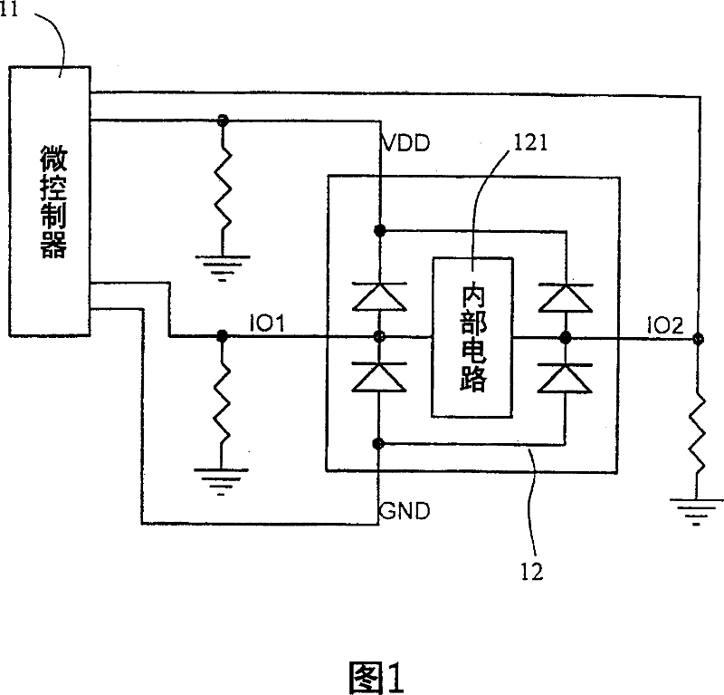
[0044] In this embodiment, a microcontroller is used to detect an integrated circuit. A microcontroller drives a high-level voltage and a low-level voltage to the pins of an integrated circuit to be tested for testing. The architecture is shown in FIG. 1 , wherein the integrated circuit 12 under test has an internal circuit 121 . The architecture shown in Figure 1 is an example of two I / O pins IO1 and IO2. If there are more than two I / O pins, the inspection method can be analogized as follows.

[0045] First, the microcontroller 11 drives the high-level voltage Vh to the ground pin GND of the integrated circuit 12 under test, and the IO1 pin and the IO2 pin of the integrated circuit 12 under test will present a Vh-diode voltage. drop (about 0.7V) high level, the power supply pin VDD of the integrated circuit 12 to be tested will present a high level of Vh-2 times the diode voltage drop, and at this time, the microcontroller 11 reads the The potentials of the IO1 pin, the IO2 ...

Embodiment 2

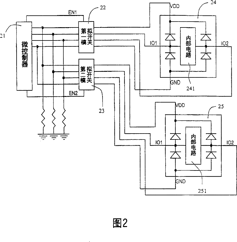
[0050] In this embodiment, a microcontroller is used to detect a plurality of integrated circuits. A microcontroller drives a high-level voltage and a low-level voltage to the pins of a plurality of integrated circuits to be tested for testing. The micro-controller is electrically connected to the integrated circuit under test through a plurality of analog switches, and its structure is shown in FIG. The architecture shown in FIG. 2 is an example of two analog switches 22, 23 and two integrated circuits to be tested 24, 25. If the number of integrated circuits to be tested is greater than two, the number of analog switches must also be increased by the same amount. The detection method of this embodiment is based on the detection method of the preferred embodiment 1. At the same time, it takes advantage of the fast switching of the analog switch to replace the relay with a slow switching speed to increase the detection speed and reliability, and can detect Multiple integrated ...

Embodiment 3

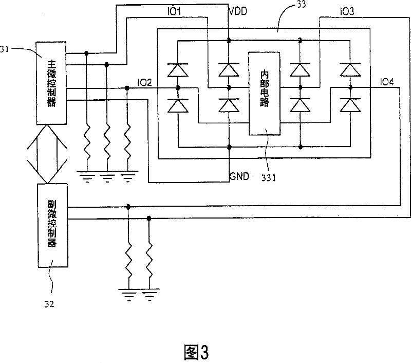
[0053] If the integrated circuit to be tested has too many pins and one microcontroller cannot test all the pins at the same time, more than two microcontrollers can be used to test the integrated circuit to be tested. As shown in FIG. 3 , it is a schematic diagram of the structure of the third preferred embodiment of the present invention. The third preferred embodiment uses a plurality of microcontrollers 31, 32 to detect an integrated circuit 33 with a large number of pins. The detection method is Drive a high-level voltage and a low-level voltage to the pins of an integrated circuit 33 under test by a main microcontroller 31 and at least one secondary microcontroller 32 for testing, wherein the integrated circuit 33 under test The power supply pin VDD, the ground pin GND, and some input-output pins IO1, IO2 are electrically connected to the main microcontroller 31, and the other input-output pins IO3, IO4 of the integrated circuit 33 to be tested are electrically connected ...


PUM


Abstract

The method incldues steps as follows: 1) high level voltage is transmitted to earthing pin of integrated circuit to be tested by microcontroller; b) potentials of power pin and other outupt-input pin for integrated circuit to be tested are red in separately by microcontroller for judging which pin is in open circuit state; c) high level voltage is transmitted to output-input pin to be tested and low level voltage to earthing pin by microcontroller; d) potentials of other output-input pin and power pin are red in by microcontroller separately to judge which output-input pin is in short circuit state with the pin and whether output-input pin to be tested or the power pin is in short circuit with the earthing pin or not.

Description

technical field [0001] The invention relates to a detection method of an integrated circuit, especially a detection method for driving a high-level voltage and a low-level voltage to a pin of an integrated circuit to be tested by means of a microcontroller for testing. Background technique [0002] Due to the fierce competition in the electronics industry, one of the methods for manufacturers to strive for profits is to reduce the cost of products. Therefore, in order to save the packaging cost of integrated circuits (ICs), many system manufacturers combine the die of integrated circuits with The COB (Chip On Board) method is directly wired on the printed circuit board. However, in the process of wire bonding and sealing of integrated circuits, this kind of production method may cause the wires to fall off or short circuit between the wires. If the defective products are not eliminated before they are assembled into finished products, unnecessary materials and waste will be ...

Claims


Application Information

Patent Timeline
Patent Type & Authority Patents(China)
IPC IPC(8): G01R31/02G01R31/26
Inventor 萧祝瓜
Owner HOLTEK SEMICON
Why Eureka
Try Eureka