
Wind driven power generating system

A wind turbine, vertical axis technology, applied in the direction of wind turbine components, wind engines, wind engines consistent with the wind direction, etc., can solve problems such as inability to generate electricity, difficult to control, reverse rotation direction, etc., to prevent overload work , easy to lead out and maintain, prevent winding effect

Inactive Publication Date: 2007-09-19
金 东 龙 +1
View PDF5 Cites 11 Cited by
  • Summary
  • Abstract
  • Description
  • Claims
  • Application Information

AI Technical Summary

Problems solved by technology

[0005] However, the above-mentioned horizontal axis wind power generator has the advantage of high transmission efficiency because the rotational torque transmission path from the blade to the generator is short, but it becomes heavy because the generator is mounted inside the movable body, and it is difficult to perform rapid torque transfer according to the wind direction. Yaw operation; when the movable body rotates more than a certain number of times, there is a problem that the wind turbine stops operating and at the same time unwinds the entangled wires to the original position
[0006] Moreover, the above-mentioned movable body is equipped with a generator inside, which is inconvenient for cooling and maintenance, etc.
In extreme times such as strong winds, for system protection such as overload of the generator, it is completely stopped by pitch control of the wing, and there is a problem that power cannot be generated.
[0007] The vertical-horizontal axis combined wind turbine (dual-rotor method) uses the wind force passing through the central part of the main blade to assist the blade to generate torque, thereby increasing the wind utilization rate per cross-sectional area, but the main blade and auxiliary blade The direction of rotation is opposite and it is difficult to make the blades. In order to stably synthesize the torque of the main blades and auxiliary blades, each pitch should be precisely controlled, but it is actually difficult to control.
[0008] In addition, the production cost is high, and there is a problem that the horizontal axis wind turbine can be completely stopped by pitch control during an emergency such as strong wind, and cannot generate electricity.

Method used


Image

  • Wind driven power generating system
  • Wind driven power generating system
  • Wind driven power generating system

Examples


Embodiment Construction

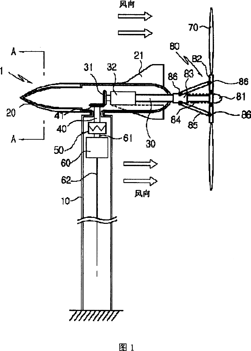
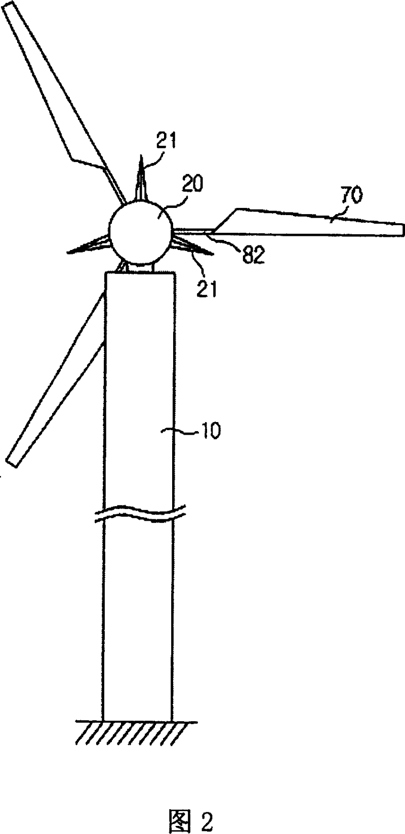
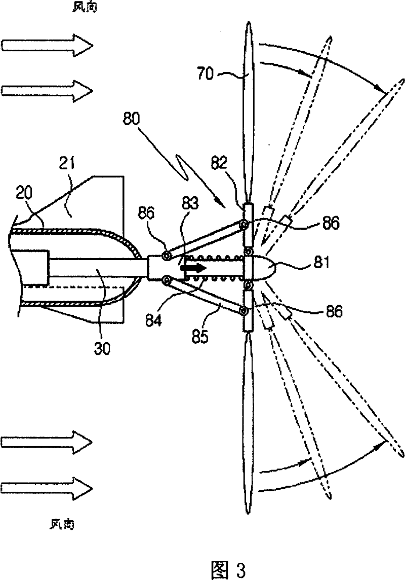
[0031] Hereinafter, the present invention will be described in detail with reference to the drawings.

[0032] Repeated explanations are omitted for parts that are the same as the traditional ones.

[0033] 1 is a sectional view of a wind generator according to the present invention, FIG. 2 is a front view of the wind generator according to the present invention, and FIG. 3 is a state diagram of variable blades in the wind generator according to the present invention.

[0034] As shown in the figure, according to the wind power generator 1 of the present invention, a rotatable streamlined movable body 20 is arranged on the upper end of a tower 10 at a certain height on the ground.

[0035] In order to reduce the weight, it is better for the above-mentioned movable body 20 to be hollow inside.

[0036] Then, three rudders 21 are radially formed on the outer surface of the movable body 20 .

[0037] Here, the rudder 21 is preferably formed toward the rear of the movable body 2...


PUM


Abstract

The present invention discloses a wind driven power generator. The wind driven power generating system comprises: a) an aerodynamic unit rotatably mounted at the top of a tower having a certain height; b) a plurality of rudders for aligning the aerodynamic unit with the direction of wind, the rudders being radially formed on the outer surface of the aerodynamic unit; c) a horizontal shaft rotatably and horizontally mounted in the aerodynamic unit, wherein one end of the outwardly from the backend of the aerodynamic unit and the other end of the horizontal shaft remains inside of the aerodynamic unit and is provided with a first bevel gear; d) a blade attached to the rear end of the horizontal shaft, wherein the blade is rotated by the wind and thus rotates the horizontal shaft; e) blade variation means disposed at the rear portion of the aerodynamic unit for slanting the blade backwards and forwards, depending on the wind pressure; f) a power generator installed inside the tower; and g) a vertical shaft for transmitting the rotating power of the horizontal shaft to the power generator, wherein one end of the vertical shaft is provided with a second bevel gear, which is engaged with the first bevel gear, and the other end thereof is connected to a rotor shaft of the power generator.

Description

technical field [0001] The present invention relates to a horizontal-vertical axis combined wind power generator system in a single-rotor mode. More specifically, it relates to automatic wind direction tracking, and there is no additional pitch control for super strong winds. The blades automatically move backward according to the spring pressure. While protecting the system, it is a single-rotor type horizontal-vertical axis combined wind turbine system that continues to generate electricity at the same time. Background technique [0002] A general wind power generator system converts the rotational energy of the blades rotating according to the wind force into electrical energy, and supplies power to various consumers. According to the direction of the shaft, it can be divided into propeller type horizontal axis wind turbine system and vertical axis wind turbine system such as gyromill type and darrieus type, or vertical-horizontal axis combined wind turbine system, etc. T...

Claims


Application Information

Patent Timeline
Patent Type & Authority Patents(China)
IPC IPC(8): F03D9/00F03D11/04F03D5/00F03D7/04B63H1/06F03D1/06
CPCY02E10/70F05B2240/2022F05B2260/4031F05B2260/78Y02E10/721Y02E10/723Y02E10/725F03D1/0658Y10S415/908F05B2260/79Y02E10/728F05B2240/2213F03D7/0236Y02E10/722F05B2250/192F03D11/02F05B2250/232F05B2260/502F03D15/00F03D15/10F03D9/25Y02E10/72E21D11/383E21D11/381E02D31/025E02D2450/105
Inventor 金东龙金荣敏
Owner 金 东 龙
Learn More