Grinding structural unit

A component and grinding disc technology, which is applied in the direction of abrasive materials, metal processing equipment, manufacturing tools, etc., can solve the problems of reduced grinding rate, reduced grinding rate of ground objects, and limitation of process width, so as to reduce the problem of load effect and increase the grinding rate , Improve the effect of process width

Inactive Publication Date: 2007-10-10
FUJIAN JINHUA INTEGRATED CIRCUIT CO LTD
View PDF6 Cites 0 Cited by
  • Summary
  • Abstract
  • Description
  • Claims
  • Application Information

AI Technical Summary

Problems solved by technology

[0006] When the surface of the object to be ground tends to be flattened, since the grinding pad 110 is also a flat surface, the object to be ground will be difficult to remove the binder in the grinding pad 110, so that the grinding rate of the object to be ground will be reduced. will decrease rapidly and sharply, so that the abrasive cannot be effectively removed and cause the residue of the abrasive
[0007] Moreover, in the application of the shallow trench isolation structure process, in order to avoid the problems that there is still too thick planarized silicon oxide (ground object) on the wafer after the wafer is planarized, which will cause the aforementioned grinding rate reduction and silicon oxide residue problems, Therefore, the overburden of silicon oxide on the silicon nitride in the active region must be controlled to be less than a predetermined height, but this will limit the process width of the silicon oxide gap fill process.
[0008] Moreover, also in the application of the shallow trench isolation structure process, for the shallow trench isolation structure process of 90nm and less than 90nm, since the process width of silicon oxide trench filling is getting smaller and smaller, the silicon nitride in the active region The height of the silicon oxide on the surface often exceeds the predetermined height, which may cause the aforementioned problems of reduced grinding rate and silicon oxide residue, making it difficult to apply the abrasive cloth chemical mechanical polishing method to the shallow isolation structure process of 90nm and less than 90nm

Method used


Image

  • Grinding structural unit
  • Grinding structural unit
  • Grinding structural unit

Examples


no. 1 example

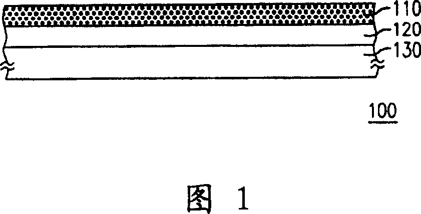
[0046] FIG. 2 is a schematic cross-sectional view of a grinding member according to a preferred embodiment of the present invention. Referring to FIG. 2 , the polishing member 200 of the present invention is composed of a polishing pad 210 , a polishing pad 220 and a polishing disc (platen) 230 .

[0047] Please continue to refer to Fig. 2, the grinding pad 210 is configured on the grinding pad 220, in the present embodiment, the main body of the grinding pad 210 is, for example, an emery cloth type (fixed abrasive) grinding pad, and the grinding pad 210 includes a plurality of abrasive grains (here In Fig. 2, for the sake of simplification, what is drawn is the whole layer of polishing pad 210 and does not draw individual abrasive grains), wherein these abrasive grains are arranged in a triangular pyramid, hexagonal pyramid or cylindrical shape and matrix, and each An abrasive grain is composed of a binder and abrasive grains (abrasive) uniformly distributed in the binder, an...

no. 2 example

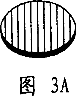
[0056] FIG. 6 is a schematic cross-sectional view of a grinding member according to another preferred embodiment of the present invention. In addition, in FIG. 6 , the same components as in FIG. 2 are denoted by the same reference numerals, and description thereof will be omitted. Referring to FIG. 6 , the grinding member 200 of the present invention is composed of a grinding pad 210 , a grinding pad 220 and a grinding disc 230 . The difference between this embodiment and the first embodiment is that the grooves 229 and the convex structures 228 are arranged on the surface 226 of the grinding pad 220 that is in contact with the grinding disc 230. At this time, the grinding pad 220 is preferably deformable. The material is, for example, rubber, and the pattern of the formed groove 229 is, for example, the patterns shown in FIGS. 3A to 3D or one of the combinations of these patterns.

[0057] When the grinding member 200 of this embodiment is used for grinding, the grinding pad...

no. 3 example

[0059] FIG. 7 is a schematic cross-sectional view of a grinding member according to another preferred embodiment of the present invention. In addition, in FIG. 7 , the same components as those in FIG. 2 are denoted by the same reference numerals, and description thereof will be omitted. Referring to FIG. 7 , the grinding member 200 of the present invention is composed of a grinding pad 210 , a grinding pad 220 and a grinding disc 230 . This embodiment differs from the first embodiment in that the surface 222 of the grinding pad 220 in contact with the grinding pad 210 is provided with grooves 225 and convex structures 224, and the surface 226 in contact with the grinding disc 230 is also provided with There are grooves 229 and protruding structures 228 , and the pattern of the formed grooves 229 is, for example, the patterns shown in FIGS. 3A to 3D or one of the combinations of these patterns.

[0060] When using the grinding member 200 of this embodiment for grinding, the gr...


PUM


Abstract

A grinding member is composed of a grinding disk, a grinding liner on said grinding disk and a grinding pad on said grinding liner. It features that said grinding liner has one concave-convex surface.

Description

technical field [0001] The invention relates to a grinding member, in particular to a grinding member capable of increasing the grinding rate of a fixed abrasive chemical mechanical polishing method. Background technique [0002] In the semiconductor process, as the size of components continues to shrink, the resolution of lithography exposure increases relatively, and with the reduction of exposure depth of field, the requirements for the level of fluctuations on the wafer surface are more stringent. Therefore, the current wafer planarization (Planarization) is completed by chemical mechanical polishing process. Its unique anisotropic grinding properties can be applied to vertical and horizontal metal Fabrication of the mosaic structure of the interconnection mechanism (Interconnects), shallow trench isolation (Shallow trench isolation, STI) fabrication of components in the front-end process, fabrication of advanced components, micro-electromechanical system planarization, ...

Claims


Application Information

Patent Timeline
Patent Type & Authority Patents(China)
IPC IPC(8): B24D9/08
Inventor 蔡腾群许加融余志展李振仲
Owner FUJIAN JINHUA INTEGRATED CIRCUIT CO LTD
Why Eureka
Try Eureka