Programmable asynchronous triggering time delayer, and method of use

A technology of trigger and delay device, applied in the field of programmable asynchronous trigger delay device, to achieve the effect of simplifying circuit structure, eliminating burr phenomenon, and facilitating change or control

Inactive Publication Date: 2008-01-09
科圆半导体(上海)有限公司
View PDF5 Cites 0 Cited by
  • Summary
  • Abstract
  • Description
  • Claims
  • Application Information

AI Technical Summary

Problems solved by technology

[0005] The technical problem to be solved by the present invention is to provide a programmable asynchronous trigger delayer and its use method, which simplifies the circuit structure by using several triggers connected in series, and solves the problem of requiring an additional gate control circuit in general asynchronous triggering. Conducive to the improvement of integrated circuit integration

Method used


Image

  • Programmable asynchronous triggering time delayer, and method of use
  • Programmable asynchronous triggering time delayer, and method of use
  • Programmable asynchronous triggering time delayer, and method of use

Examples


Embodiment Construction

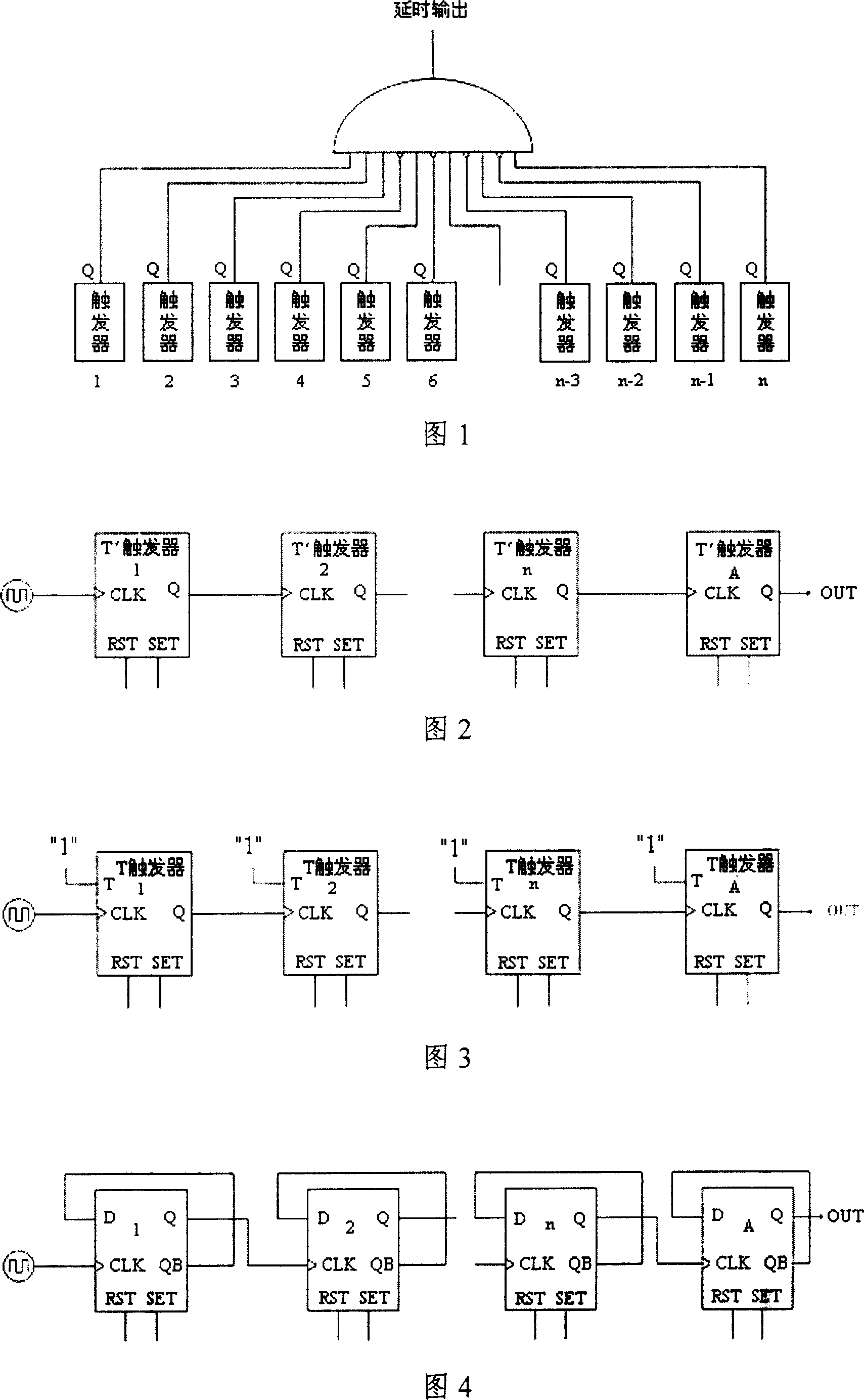
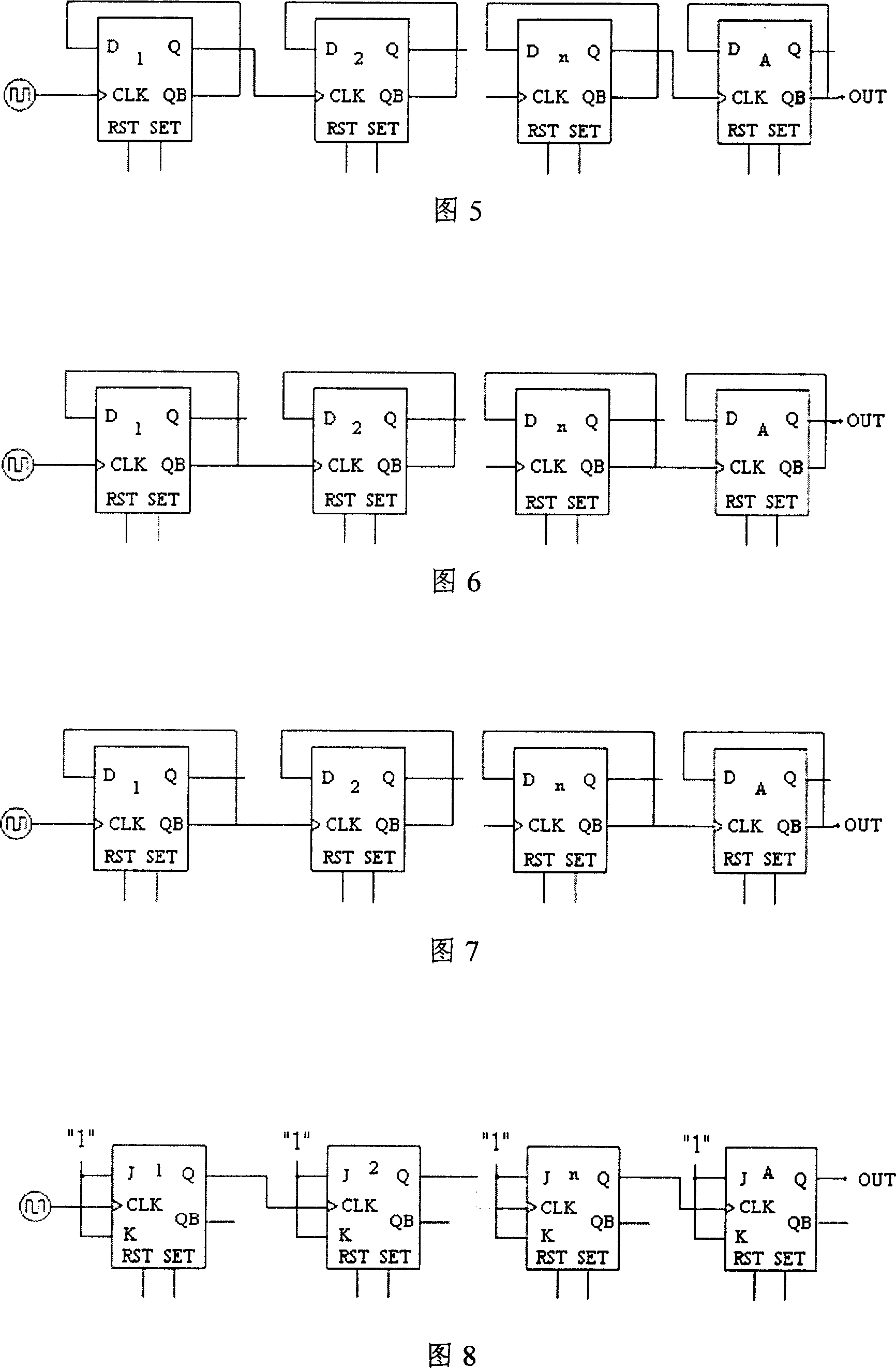
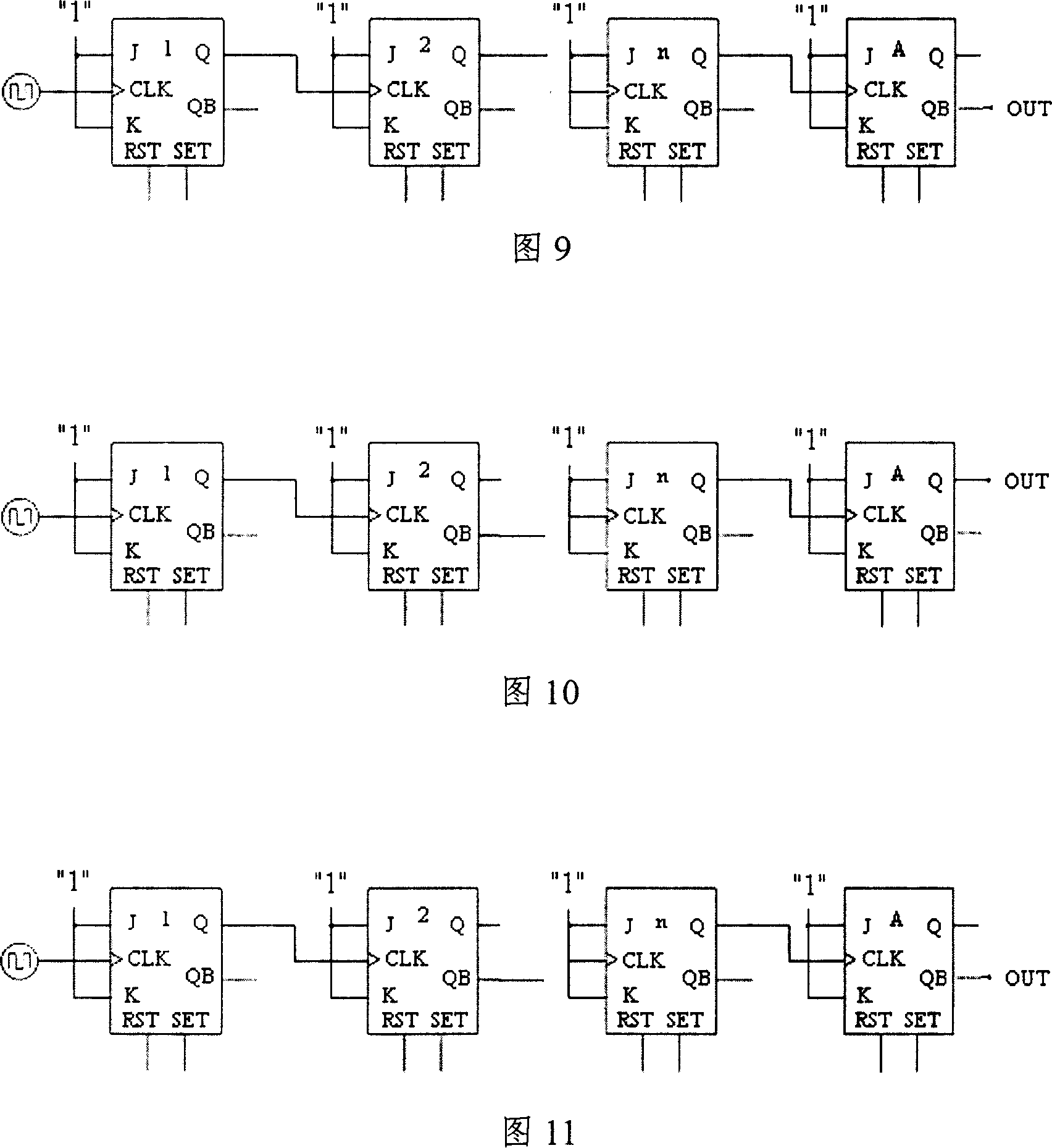
[0015] The circuit structure of the programmable asynchronous trigger delayer of the present invention is shown in Figure 2, comprises n T' flip-flops, and described n T' flip-flops are connected one by one in turn, and the output terminal of the previous T' flip-flop is connected to the next The CLK ends of the T' flip-flops are connected, and the CLK ends of the first T' flip-flops are connected to the external clock pulse. The SET and RST ends of these T' flip-flops are count value input ends, and the first T ' flip-flop to the nth T' flip-flop respectively corresponding to the lowest bit to the highest bit of the input binary data, the present invention also includes the n+1th T' flip-flop, the CLK terminal of the T' flip-flop is connected to the nth The output terminal of the T' trigger, the output terminal of the T' trigger is a delay signal output terminal, and the number n of the T' trigger is greater than or equal to the binary count obtained by dividing the delay time...


PUM


Abstract

The invention includes following parts and structures: triggering delayer includes several pieces of T'trigger connected to each other one by one in sequence; output end of the previous T'trigger is connected to CLK end of the next T'trigger; CLK end of first T'trigger is connected to external clock pulse; output end of the last T'trigger is the output end of the delayed signal. Method of use is as following: setting up RST end and SET end of each trigger according to delay time, and then disabling two pieces of input end; inputting fixed clock pulse. Using the output of final trigger as delayed output signal, the invention simplifies structure of circuit, and solves the issue that additional gate control circuit is needed in general asynchronous trigger. Features are: easy of changing or controlling delayed time, and suitable to instance of large delayed time needed.

Description

technical field [0001] The invention relates to a programmable asynchronous trigger delayer, in particular to a programmable asynchronous trigger delayer composed of triggers. The invention also relates to a method for using a programmable asynchronous trigger delayer. Background technique [0002] In the existing electronic measurement and integrated circuit design technology, the delay circuit is generally implemented by means of resistance and capacitance delay or synchronous trigger latch trigger or asynchronous trigger. [0003] Resistor-capacitor delay is not only difficult to control the delay accuracy, but also requires a large layout area, especially where a large delay is required (such as a second-level delay). [0004] Regardless of whether the synchronous trigger latch flip-flop or the general asynchronous trigger method is used, in addition to the oscillator and flip-flop, some additional gate logic control circuits are required, as shown in Figure 1. Synchro...

Claims


Application Information

Patent Timeline
Patent Type & Authority Patents(China)
IPC IPC(8): H03K5/13H03K5/14
Inventor 吴镔
Owner 科圆半导体(上海)有限公司
Why Eureka
Try Eureka