Fuel injection valve for internal combustion engines and a method for hardening said valve

一种燃料喷射阀、内燃机的技术,应用在燃料喷射装置、特殊燃料喷射装置、机械设备等方向,能够解决硬化方法不再能满足这种应用等问题,达到改善可加工性、减小原始硬度、加工余量减小的效果

Inactive Publication Date: 2008-01-30
ROBERT BOSCH GMBH
View PDF6 Cites 0 Cited by
  • Summary
  • Abstract
  • Description
  • Claims
  • Application Information

AI Technical Summary

Problems solved by technology

The steels used hitherto and the hardening methods used for them are no longer adequate for this application

Method used


Image

  • Fuel injection valve for internal combustion engines and a method for hardening said valve
  • Fuel injection valve for internal combustion engines and a method for hardening said valve

Examples


Embodiment Construction

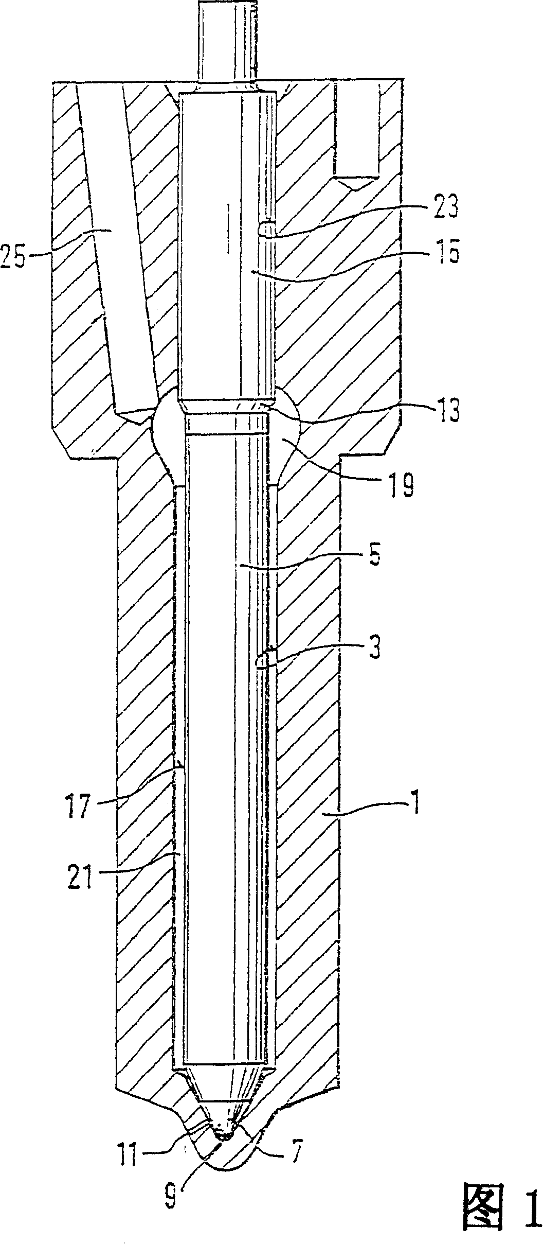
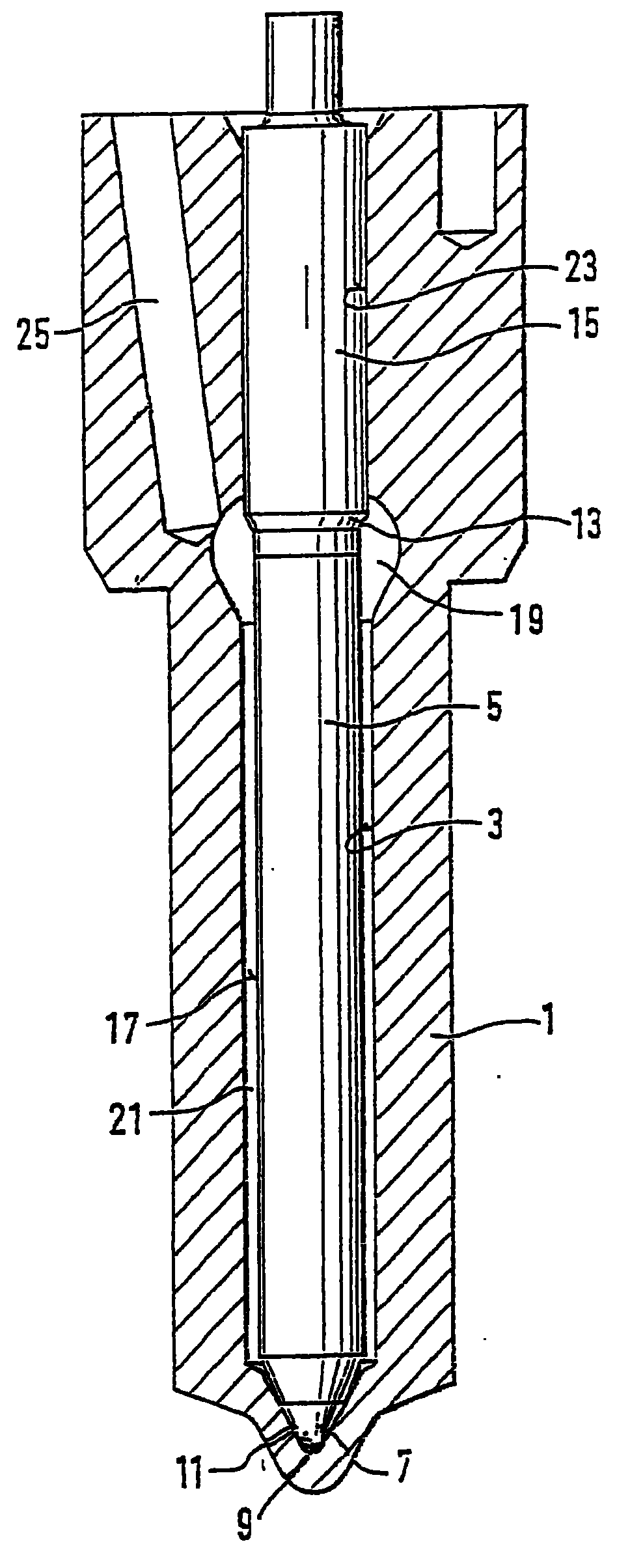
[0012] The fuel injector shown in FIG. 1 has a valve body 1 in which a valve needle 5 is arranged longitudinally displaceable in a bore 3 . A substantially conical valve seat 9 is formed at the end of the bore 3 on the combustion chamber side, in which at least one injection opening 11 is formed, which connects the bore 3 to the combustion chamber of the internal combustion engine. The valve needle 5 has a guide section 15 through which the valve needle is guided in a sealing manner in a guide section 23 of the bore 3 . The valve needle 5 tapers in the direction of the valve seat 9 and forms a pressure shoulder 13 and transitions into a rod section 17 of reduced diameter. At the end of this section, a substantially conical valve sealing surface 7 is formed on the valve needle 5, which cooperates with the valve seat 9 and when it rests on the valve seat 9, it opposes at least one injection hole 11. Hole 3 is closed.

[0013] A pressure chamber 19 is formed at the level of the...


PUM


Abstract

A fuel injection valve for internal combustion engines, comprises a valve body (1) and at least one injection opening (11), provided therein. Fuel can be injected through said opening into the combustion chamber of the internal combustion engine in a controlled manner by a valve needle (5) which cooperates with a valve seat (9), provided in the valve body (1). Said valve body (1) is composed of a high-alloy hot-work steel, hardened by a carburizing method.

Description

technical field [0001] The invention relates to a fuel injection valve for an internal combustion engine and a method for hardening the valve body. Background technique [0002] Various methods of hardening steel are known from the prior art. This will affect the wear resistance and stability of the material as well as the processability. An example of this is so-called carburization, in which carbon is infiltrated into the surface layers of the material. A method related to this is described, for example, in document US Pat. No. 4,836,864. A further possibility is the nitriding of the steel, in which nitrogen is impregnated in layers near the surface of the workpiece. Such hardened and treated steels are used in fuel injection valves, in particular for compression-ignition internal combustion engines and as described, for example, in DE 19618650 A1 in order to prolong the service life of the steel. In the trend of further engine improvements, especially in trucks, the t...

Claims


Application Information

Patent Timeline
Patent Type & Authority Patents(China)
IPC IPC(8): F02M61/16C23C8/22
CPCC23C8/22F02M61/168F02M2200/9061F02M61/166
Inventor 迪特尔·利特克阿尔弗雷德·霍赫弗朗茨·沃尔夫
Owner ROBERT BOSCH GMBH
Why Eureka
Try Eureka