
Interference type silicon base chip optical gyroscope

A micro-optical and interferometric technology, which is used in Sagnac effect gyroscopes, optical waveguides, steering sensing devices, etc.

Inactive Publication Date: 2008-02-06
ZHEJIANG UNIV
View PDF6 Cites 0 Cited by
  • Summary
  • Abstract
  • Description
  • Claims
  • Application Information

AI Technical Summary

Problems solved by technology

Compared with MEMS gyroscopes, MOG is slightly larger in size, but its accuracy is 1 to 2 orders of magnitude higher.

Method used


Image

  • Interference type silicon base chip optical gyroscope
  • Interference type silicon base chip optical gyroscope
  • Interference type silicon base chip optical gyroscope

Examples


Embodiment Construction

[0020] The micro-optical gyroscope replaces the optical fiber with a silicon-based optical waveguide, and integrates other optical devices on the silicon chip. The structural composition adopted by the present invention is:

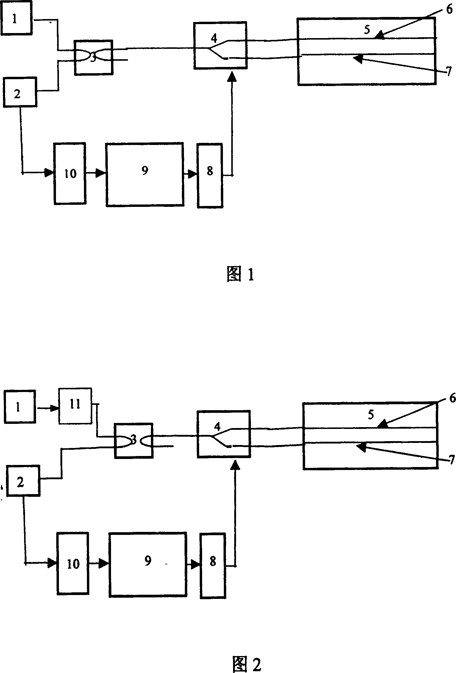
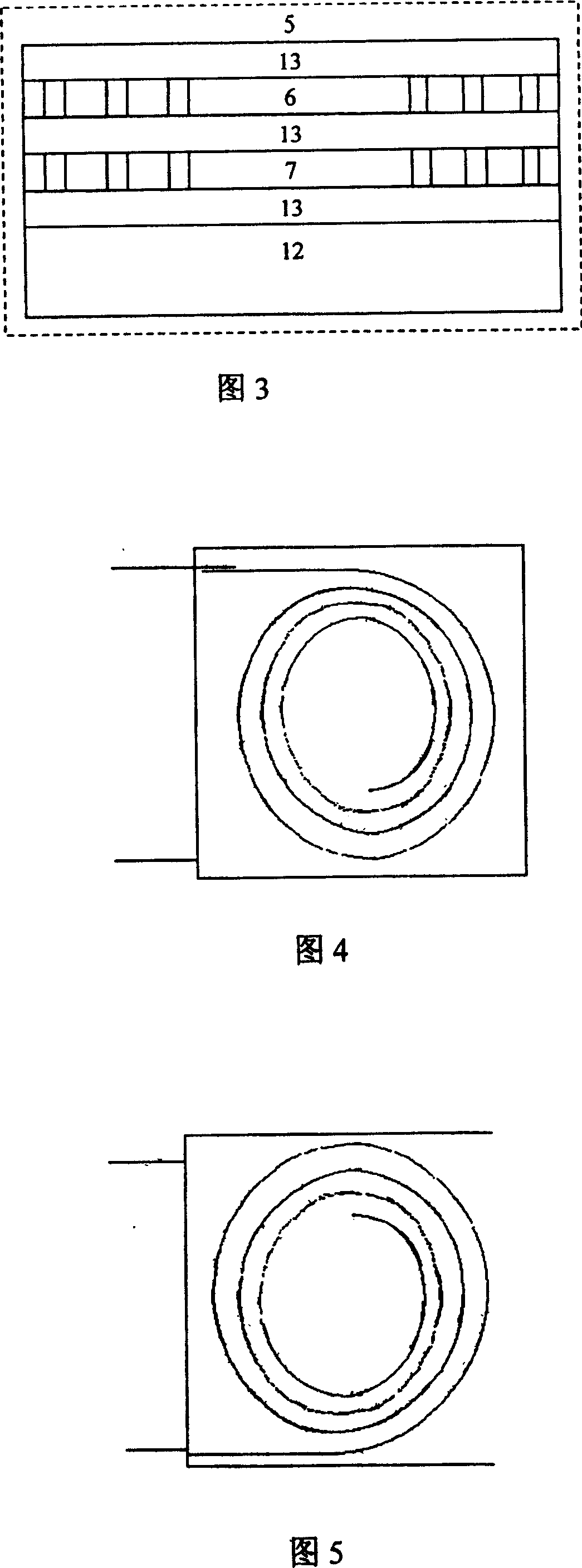
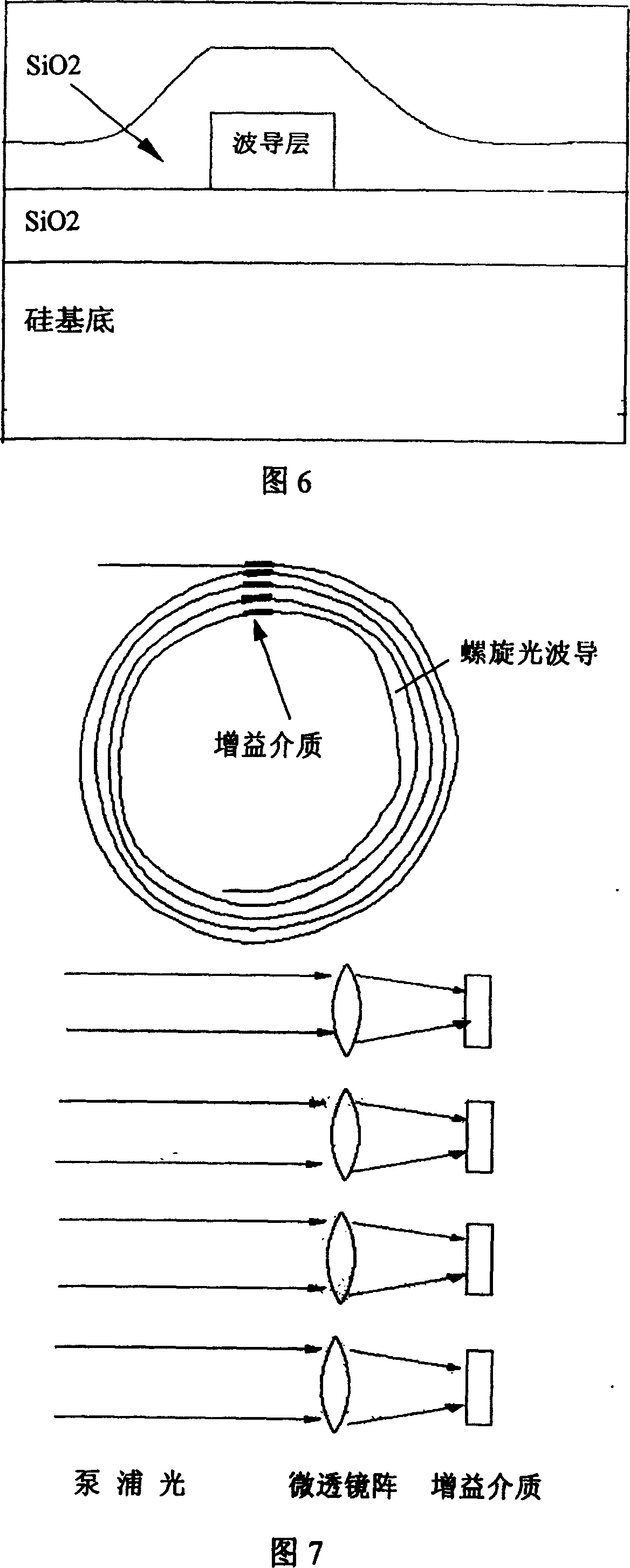
[0021] As shown in Figure 1, the interferometric micro-optical gyroscope (IMOG) structure. The interferometric silicon-based chip micro-optical gyroscope has a detector 2, a sampling circuit 10, a digital signal processing circuit 9, a modulation drive circuit 8, a Y waveguide modulator 4, a beam splitter 3 connected in sequence, the beam splitter 3 and the light source 1, The detector 2 is connected, and the Y-waveguide modulator 4 is connected with the spiral optical waveguide 5. The spiral optical waveguide 5 has a Si substrate 12 of the spiral optical waveguide, and the upper spiral optical waveguide 6 and the lower layer Spiral optical waveguide7. The upper helical optical waveguide 6 and the lower helical optical waveguide 7 are located on the same...


PUM


Abstract

The interferential silicon chip micro optical gyroscope has successively connected detector, sample circuit, DSP circuit, modulating driver circuit, Y-waveguide modulator, beam splitter, light source, and spiral light waveguide with upper layer spiral light waveguide, lower layer spiral light waveguide and Si substrate for spiral light waveguide. The present invention is superior to optical fiber gyroscope, which has great fiber length and great temperature and vibration influence, and has small size, high reliability and high precision. The present invention is also superior to micro mechanical gyroscope, and has light source, optical device and processing circuit integrated on one chip and thus high precision and high reliability.

Description

technical field [0001] The invention relates to an interference type silicon-based chip micro-optical gyroscope. technical background [0002] High precision, high reliability, and miniaturization have always been the goals pursued by inertial navigation gyroscopes. Optical gyroscopes using the Sagnac effect are in line with this goal compared with various first-generation mechanical gyroscopes. Therefore, the laser gyroscope (ROG) in the optical gyroscope has become the second generation gyroscope, which is an innovative product in the 1970s; the fiber optic gyroscope (FOG) is the third generation gyroscope, which is an innovative product in the 1990s. At present, FOG has entered full-scale application; micro-optical gyroscope (MOG) can be said to be the fourth generation gyroscope, and it is a new product of the 21st century. Compared with the MEMS gyroscope, the MOG is slightly larger in size, but its accuracy is 1 to 2 orders of magnitude higher. Compared with the fib...

Claims


Application Information

Patent Timeline
Patent Type & Authority Patents(China)
IPC IPC(8): G01C19/72G01C19/64G02B6/10G01C19/58
Inventor 杨国光吴兴坤徐建锋白剑刘成侯西云梁宜勇
Owner ZHEJIANG UNIV
Learn More