

Optical guidance moving direction prediction method
A technology of moving direction and optical guidance, which is applied in the field of optical indicators, and can solve problems such as mouse indicator shaking, errors, and movement errors
- Summary
- Abstract
- Description
- Claims
- Application Information
AI Technical Summary
Problems solved by technology
Method used
Image

Examples
Embodiment Construction
[0028] The present invention will be described with the prediction of the moving direction of the optical mouse. When the image sensing device of the optical mouse captures the light reflected back from the desktop, it will be converted into digital data and sent to the digital signal processor for direction prediction and judgment. .
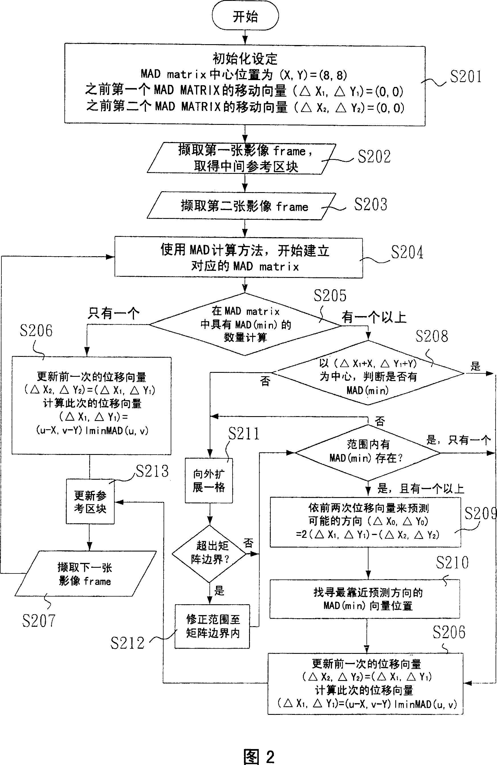
[0029] Regarding the moving direction prediction method in the digital signal processor of the present invention, please refer to the action flow chart shown in Fig. 2, first carry out initial setting (step S201), be about to set the central position of MAD matrix as (X, Y) =(8,8), and set the moving vector of the first MAD matrix as (ΔX1, ΔY1)=(0,0), and set the moving vector of the second MAD matrix as (ΔX2, ΔY2)=( 0,0). Of course, the center position of the MAD matrix is determined by the frame size, and is not limited to the set value in this example.
[0030] After that, the image sensing device will continue to capture the first image...
PUM
 Abstract
Description
Claims
Application Information