Horizontal inclined rotary fluidized bed desulfurizing reactor

A technology of inclined rotation and reactor, which is applied in the direction of chemical instruments and methods, chemical/physical processes, and separation of dispersed particles, which can solve the problems of low desulfurization reaction efficiency and local accumulation

Inactive Publication Date: 2008-02-20
HARBIN INST OF TECH
View PDF2 Cites 0 Cited by
  • Summary
  • Abstract
  • Description
  • Claims
  • Application Information

AI Technical Summary

Problems solved by technology

[0003] In order to solve the problem of low desulfurization reaction efficiency caused by the formation of local accumulations and dead zones when the gas velocity is low and the formation of a large number of bubbles and embolisms when the gas velocity is high in the prior art, a horizontal tilting rotary Fluidized bed desulfurization reactor

Method used


Image

  • Horizontal inclined rotary fluidized bed desulfurizing reactor
  • Horizontal inclined rotary fluidized bed desulfurizing reactor
  • Horizontal inclined rotary fluidized bed desulfurizing reactor

Examples


specific Embodiment approach 1

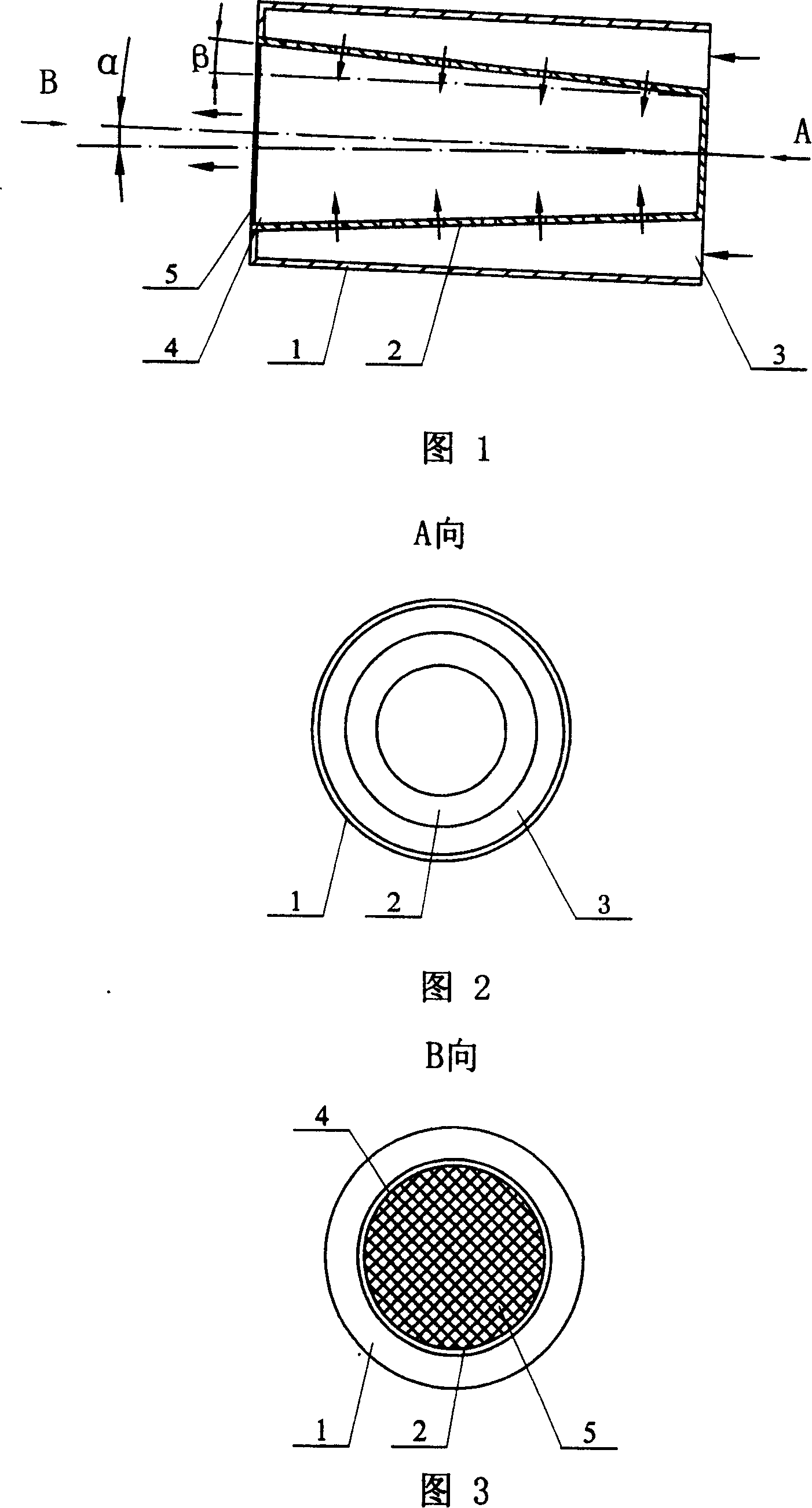
[0005] Embodiment 1: (see Fig. 1-Fig. 3) the horizontal inclined rotating fluidized bed desulfurization reactor described in this embodiment has an inner and outer double-tube structure, which includes an outer tube 1 and an inner tube 2, and the inner tube 2 is placed in the inner tube 2. In the outer cylinder 1, a gas inlet channel is formed between the inner cylinder 2 and the outer cylinder 1. The outer cylinder 1 is a cylindrical straight cylinder, the inner cylinder 2 is a truncated cone, and the circumferential wall of the inner cylinder 2 is an air distribution plate structure. The cone angle β is 0.5-12 degrees, the small-diameter end of the inner cylinder 2 is closed, the annular channel inlet 3 is formed between the small-diameter end of the inner cylinder 2 and the outer cylinder 1, the large-diameter end of the inner cylinder 2 is the gas outlet 4, and the inner cylinder The outer wall of the large-diameter end of 2 and the outer cylinder 1 are sealed and connected...

specific Embodiment approach 2

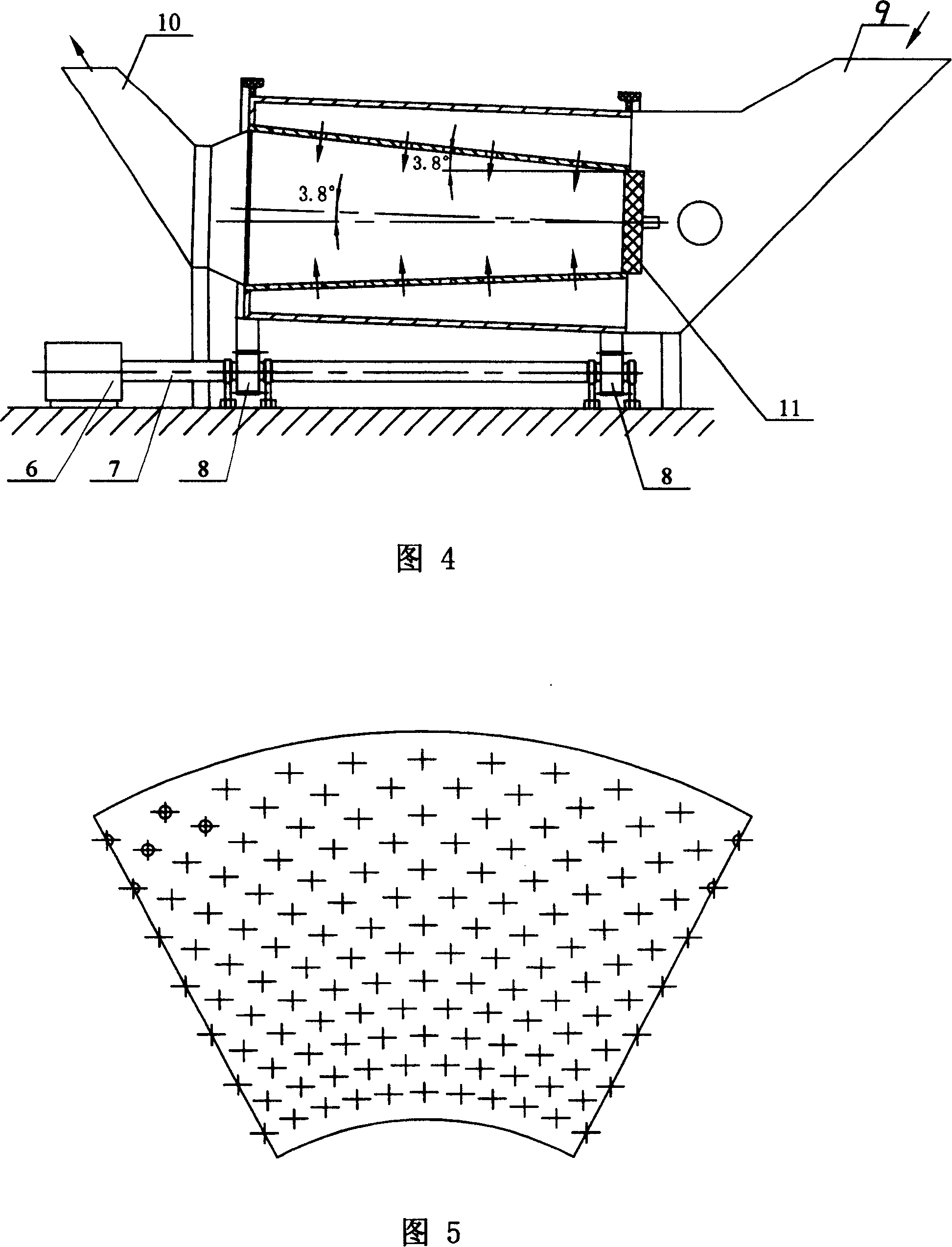
[0006] Embodiment 2: (see Figures 1 to 3) The difference between this embodiment and Embodiment 1 is that the cone angle β of the inner cylinder 2 is 2 degrees, and the angle formed between the axis of the reactor and the horizontal plane is α is 3.0 degrees. Other components and connection relationships are the same as in the first embodiment. The temperature is 165℃, with 3000ppm SO 2 , the flow is 620000m 3 The gas per hour enters the small diameter end of the inner cylinder 2 and the outer cylinder 1 to form an annular channel inlet 3 and the inner cylinder 2. The treated gas, after desulfurization reaction, contains SO 2 The concentration dropped to 100ppm, and the desulfurization efficiency was 96.6%.

specific Embodiment approach 3

[0007] Embodiment 3: (see Figures 1 to 3) The difference between this embodiment and Embodiment 1 is that the cone angle β of the inner cylinder 2 is 3.9 degrees, and the angle formed between the axis of the reactor and the horizontal plane is α is 3.9 degrees. Other components and connection relationships are the same as in the first embodiment. The temperature is 160℃, with 2400ppm SO 2 , the flow is 600000m 3 The gas per hour enters the small diameter end of the inner cylinder 2 and the outer cylinder 1 to form an annular channel inlet 3 and the inner cylinder 2. The treated gas, after desulfurization reaction, contains SO 2 The concentration dropped to 200ppm, and the desulfurization efficiency was 91.6%.


PUM


Abstract

The present invention provides one kind of horizontal inclined rotary fluidized bed desulfurizing reactor. The desulfurizing reactor is one double-layer structure including a truncated cone inner barrel with grid plate structure in the side wall, closed small caliber end and great caliber end as the gas outlet; and an outer barrel. There is a ring inlet channel formed between the small caliber end of the inner barrel and the outer barrel, the outer wall of great caliber end of the inner barrel is connected to the outer barrel, and the inclined reactor has outlet end higher than the inlet end. The present invention combines the fluidizing pneumatic force and the rotary centrifugal force well to realize the full reaction between SO2 and the desulfurizing agent grains, and has long reaction gas remaining period, high utilization rate one desulfurizing agent, and high desulfurizing efficiency up to 90-97 %.

Description

technical field [0001] The invention relates to the field of environmental protection for treating gas pollutants in flue gas, in particular to the structural design of a horizontal rotary fluidized bed desulfurization reactor. Background technique [0002] Fluidized beds are widely used in energy, environmental protection and chemical fields. The desulfurization reactor is the core device of the desulfurization process. Its technology and desulfurization indicators will restrict and determine the efficiency of the desulfurization process. When the inlet is fed, the gas drives the material to move and fluidize in the reactor, and neutralization reaction occurs to achieve the purpose of desulfurization. The inner cylinder of the existing horizontal fluidized bed desulfurization reactor is a straight cylinder. Due to the effect of gravity, the material is not uniformly fluidized in the reactor. When the gas velocity is low, the local gas cannot be fluidized, which is easy to ...

Claims


Application Information

Patent Timeline
Patent Type & Authority Patents(China)
IPC IPC(8): B01D53/83B01D53/50B01J8/24
Inventor 陆慧林郑建祥何玉荣赵云华尹丽洁
Owner HARBIN INST OF TECH
Why Eureka
Try Eureka