Pivoting type gearbox

A gearbox and pivot technology, which is applied in the field of pivot gearboxes, can solve problems such as heat generation of pivot gearbox components, complex movement of pivot gearboxes, and insufficient bridge rigidity, so as to reduce heat damage, Strong ability to transmit torque and small size

Inactive Publication Date: 2008-04-30
SHANGHAI JIAOTONG UNIV
View PDF3 Cites 0 Cited by
  • Summary
  • Abstract
  • Description
  • Claims
  • Application Information

AI Technical Summary

Problems solved by technology

Since dredgers often work in harsh sea conditions, the hull will move, and the pivotal gearbox will follow the movement of the hull. At the same time, since the pivotal gearboxes are all installed on the bridge frame, the bridge frame must often rotate according to construction requirements. Therefore During dredger construction operations, the pivoting gearbox will generate very complex movements
For the pivotal gearbox in complex motion, due to the deformation of the hull during use, insufficient rigidity of the bridge, the concentricity of the pivot of the gearbox and the shaft of the bridge, and the lateral movement of the bridge, etc., the pivotal gearbox will be caused. Gear box parts heating and damage

Method used


Image

  • Pivoting type gearbox

Examples


Embodiment Construction

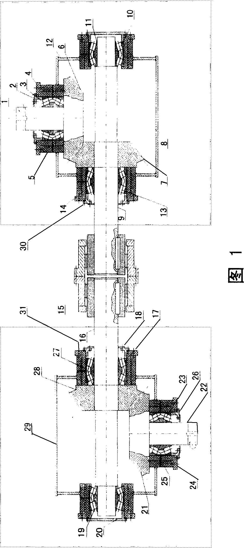
[0016] As shown in Figure 1, the present invention comprises: the box body 30 that contains input shaft, the box body 31 that contains output shaft and gear coupling 15, described box body 30 that contains input shaft includes: input shaft 1, the first A chuck 2, input shaft bearing 3, first bearing seat 4, first steel shell 5, first bevel gear 6, second bevel gear 7, first shaft 8, second shaft 9, first bearing 10, card Spring 11, the first gear case case 12, the second bearing 13 and the second bearing seat 14, the input shaft 1 is supported by the input shaft bearing 3 outside it, the first chuck 2 is fixedly connected with the first bearing seat 4 by bolts , the first bearing seat 4 is connected with the first steel shell 5 outside by bolts, the first bevel gear 6 at the top of the input shaft 1 is set in the first gearbox case shell 12, and the second bevel gear 7 is set in the second At the top of the shaft 9, the first shaft 8 is supported by the first bearing 10 at the...


PUM


Abstract

The pivot type gear box is belongs to the field of gear transmission in mechanical engineering. The present invention includes box containing input shaft, box containing output shaft and toothed shaft coupler. The box containing input shaft includes input shaft, the first chuck, input shaft bearing, the first bearing seat, the first steel casing, the first bevel gear, the second bevel grea, the first shaft, the second shaft, the first bearing, clamp spring, the first gear box casing, the second bearing and the second bearing seat. The present invention has simple structure, standard parts, easy manufacture, and low production cost.

Description

technical field [0001] The invention relates to a device belonging to the technical field of mechanical transmission, in particular to a pivotal gear box. Background technique [0002] Pivot gearboxes are specially used on cutter suction, bucket wheel or blower suction dredging vessels. These types of dredgers have a slot in the front half of the hull, and a bridge frame is placed in the slot. Equipment such as underwater mud pumps and cutter heads are installed on the bridge frame. The bridge frame can rotate around two left and right bearings placed on the hull to change the dredging depth. The submersible mud pumps on the bridge are directly driven by a deck-mounted diesel engine through a bridge-mounted pivot gearbox. Since the shaft driving the submersible mud pump needs to follow the bridge to rotate at any practical angle, the pivot gearbox must be installed between the left and right bearings of the bridge. [0003] Found through document retrieval to prior art, ...

Claims


Application Information

Patent Timeline
Patent Type & Authority Patents(China)
IPC IPC(8): F16H1/20F16H57/02F16C3/02F16H57/021
Inventor 谭家华王迎光
Owner SHANGHAI JIAOTONG UNIV
Why Eureka
Try Eureka