Reactor and fuel cell system therewith
A reactor, catalytic reaction technology, used in fuel cells, chemical/physics/physicochemical reactors, circuits, etc.
- Summary
- Abstract
- Description
- Claims
- Application Information
AI Technical Summary
Problems solved by technology
Method used
Image

Examples
no. 1 example
[0038] Refer below Figures 1 to 4B A first embodiment of the present invention is described.
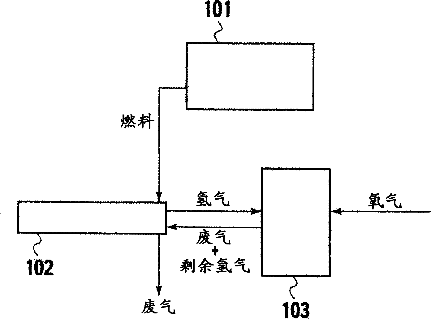
[0039] The fuel cell system according to the first embodiment is provided with a fuel tank 101 , a reformer 102 and a fuel cell stack 103 .
[0040] The fuel cell stack 101 contains a fuel for fuel cells, such as a mixed fluid of dimethyl ether (DME) and water or a mixed fluid of methanol and water. A fuel tank 101 is provided with a pressure vessel configured to be detachably connected.
[0041] The reformer 102 is connected to the fuel tank 101 by a flow line or any other suitable means. The reformer 102 receives fuel from the fuel tank 101 and facilitates a reforming reaction that converts the fuel into a hydrogen-containing reformed gas. The fuel may not only be in a liquid phase, but also in a gaseous phase formed by evaporation of the fuel. At least one reactor 100 is disposed in the bottom plate of the reformer 102, the details of which will be described below. In consid...
no. 2 example
[0080] A second embodiment of the present invention will be described below with reference to FIGS. 5A and 5B. In the following description, elements substantially the same as any of the elements described above refer to the same symbols, and detailed descriptions thereof are omitted.
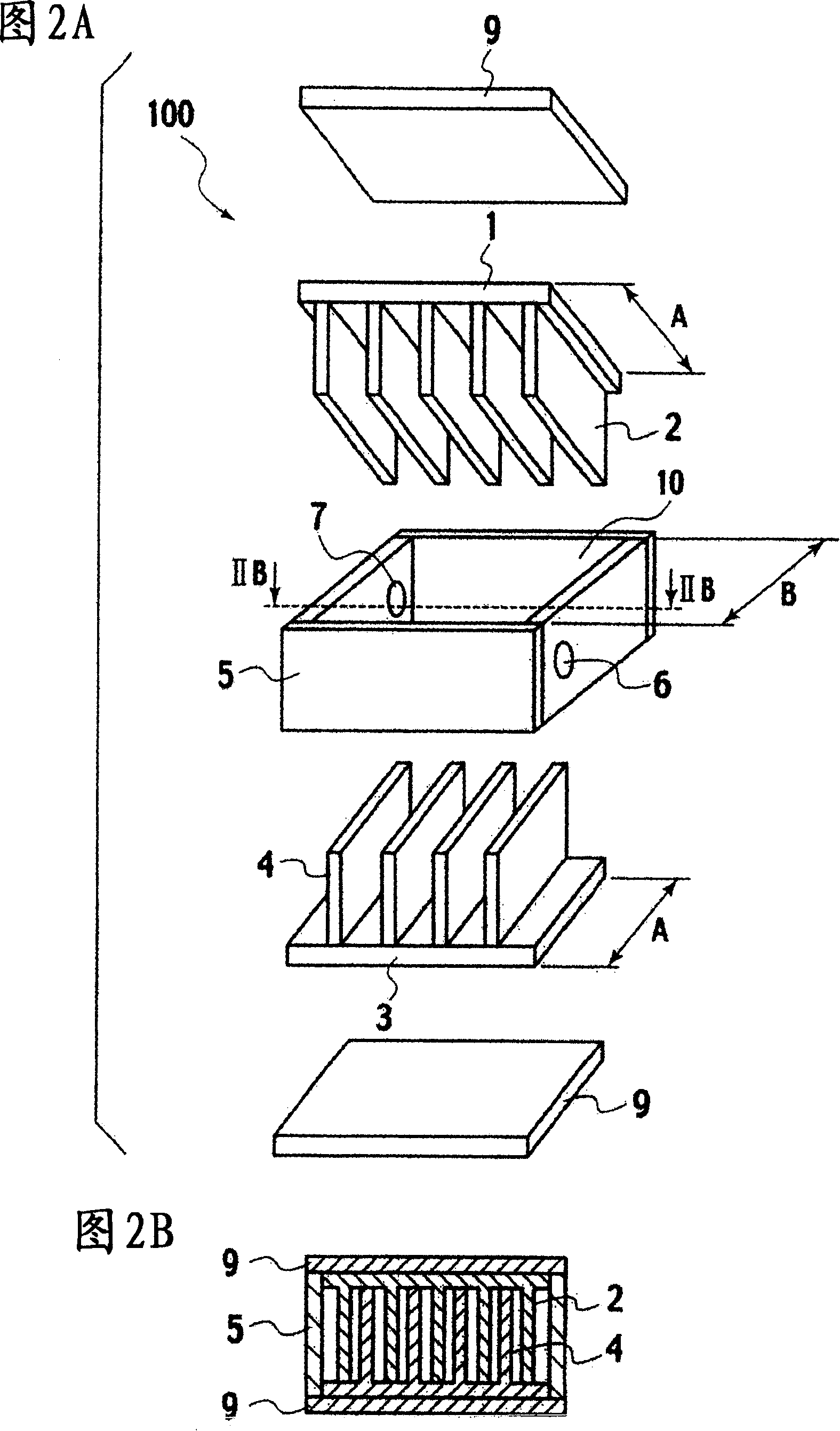
[0081] The reactor 100 according to the second embodiment is generally provided with a microchannel (first member) 1, a microchannel (second member) 3, a casing 11 for accommodating the microchannels 1, 3 and a cover for covering them. A pair of lids on top and bottom9.
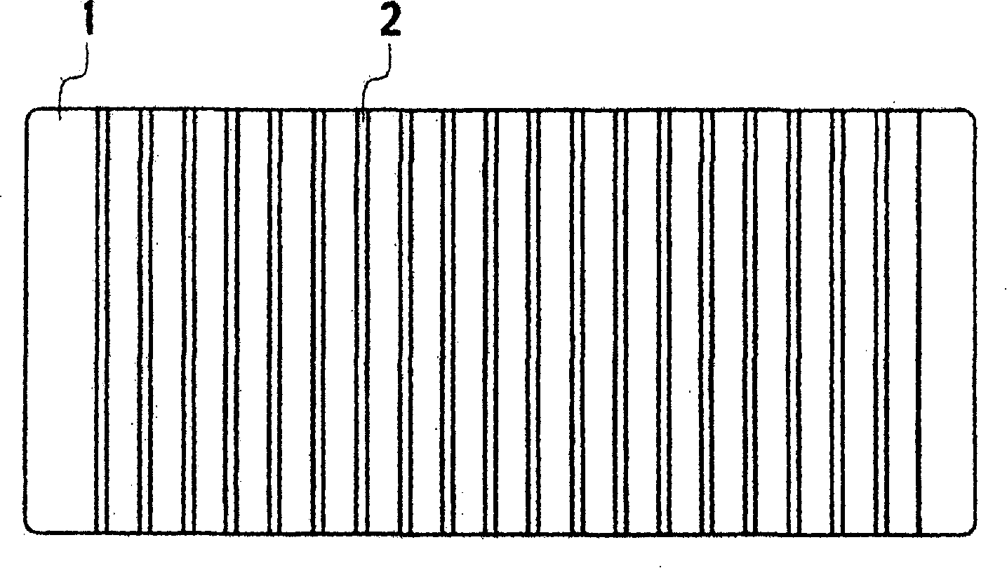
[0082] The microchannels 1, 3 are formed from the base material by machining. The microchannel 1 is provided with a plurality of protrusions (first protrusions) 2 , and the microchannel 3 is provided with a plurality of protrusions (second protrusions) 4 . Compared with the first embodiment described above, the protrusions 2 or 4 are not completely provided as gaps corresponding to the counterpart protrusions. In the exampl...
no. 3 example
[0097] Below, refer to Figure 7 A third embodiment of the present invention is described. In the following description, elements substantially the same as any of the elements described above refer to the same symbols, and detailed descriptions thereof are omitted.
[0098] The reactor 100 according to the third embodiment is generally provided with a microchannel (first member) 31, a microchannel (second member) 33, a microchannel 35, a microchannel for receiving the microchannels 31, 33, 35 Housing 37 and cover 41 for covering the top thereof.
[0099] The microchannels 31, 33, 35 are formed from the base material by machining. The microchannel 31 is provided with a plurality of protrusions 34 . The grooves between the protrusions 34 extend from one side of the microchannel 31 to the other. The base material, mechanical processing method and catalyst supported thereon are basically the same as those of the above-mentioned first embodiment, and the detailed description th...
PUM
| Property | Measurement | Unit |
|---|---|---|
| sintering temperature | aaaaa | aaaaa |
| power output | aaaaa | aaaaa |
| diameter | aaaaa | aaaaa |
Abstract
Description
Claims
Application Information
 - R&D
- Intellectual Property
- Life Sciences
- Materials
- Tech Scout
- Unparalleled Data Quality
- Higher Quality Content
- 60% Fewer Hallucinations
Browse by: Latest US Patents, China's latest patents, Technical Efficacy Thesaurus, Application Domain, Technology Topic, Popular Technical Reports.
© 2025 PatSnap. All rights reserved.Legal|Privacy policy|Modern Slavery Act Transparency Statement|Sitemap|About US| Contact US: help@patsnap.com