

Divider plate for an inlet port, sand core for forming an inlet port, and cylinder head
A technology of air inlet and partition plate, which is applied in the direction of core, cylinder head, casting and molding equipment, etc., can solve the problems such as the inability to fully suppress the position shift of the partition plate and the inability to absorb thermal expansion, and achieves easy deburring operation, The effect of suppressing position shift and improving product quality
- Summary
- Abstract
- Description
- Claims
- Application Information
AI Technical Summary
Problems solved by technology
Method used
Image

Examples
no. 1 Embodiment approach
[0042] First, the cylinder head 10 having the partition plate 100 for the intake port 14 which is the premise of the present invention will be described. In addition, in the following description, the partition plate 100 for the inlet port 14 is also called "the swirl plate 100".
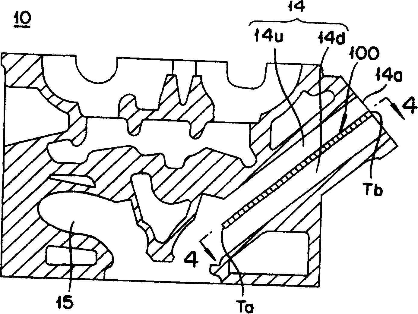
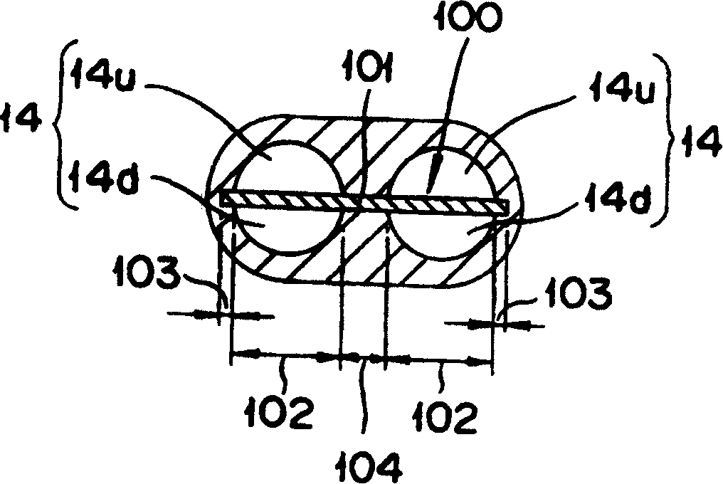
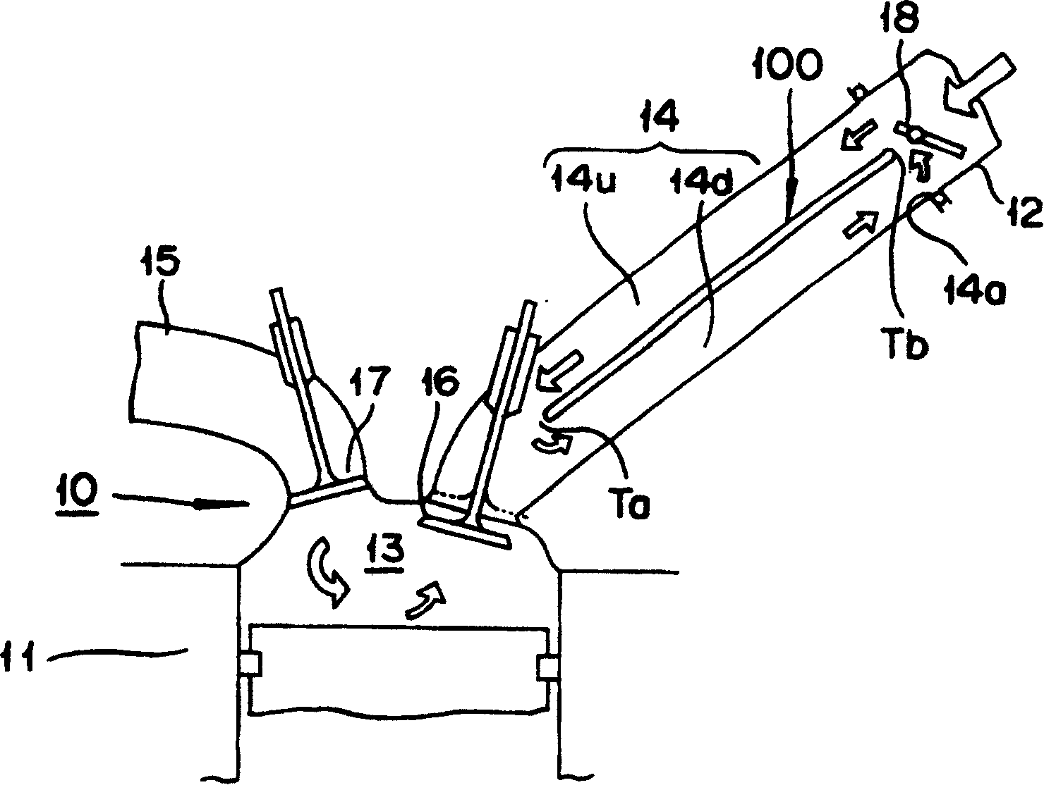
[0043] figure 1 is a schematic sectional view showing a cylinder head 10 of an engine, figure 2 is a sectional view of the air inlet 14 perpendicular to the centerline, image 3 is a schematic diagram showing the airflow state of the engine, Figure 4 is along figure 1 A schematic sectional view of line 4-4.
[0044] refer to Figure 1 ~ Figure 4 , the cylinder head 10 has: it is arranged on the top of the cylinder block 11, and the intake air flow composed of air or gas fuel from the intake manifold 12 is introduced into the intake port 14 in the cylinder bore 13; Exhaust port 15 for the exhaust gas after combustion. The air inlet is roughly divided into a double connection type and a split...
no. 2 Embodiment approach
[0098]10(A) is a plan view showing a swirl plate 100a according to the second embodiment, FIG. 10(B) is a cross-sectional view taken along line 10B-10B in FIG. 10(A), and FIG. 10(C) is for explanation. It is a figure which changes the length of the swirl plate 100a of 2nd Embodiment in a casting process. In addition, the same code|symbol is attached|subjected to the same member as 1st Embodiment, and description is abbreviate|omitted.
[0099] The swirl plate 100a of the second embodiment has a seal forming portion 130 for forming a seal portion between the intake ports 14 in addition to the structure of the swirl plate 100 of the first embodiment. The seal forming portion 130 is provided at a position closer to the intake side end portion Tb than the position at which the promoting portion 110 is provided in the inner overcast portion 104 . The seal forming part 130 has a punched hole 131 formed through the inner square overcast part 104 leaving an overcast part of a necessa...
no. 3 Embodiment approach
[0104] Figure 11 It is a top view showing the die core 200a provided with the swirl plate 100b of the third embodiment in advance. In addition, the same code|symbol is attached|subjected to the same member as 1st and 2nd embodiment, and description is abbreviate|omitted.
[0105] The third embodiment is compatible with the first and second cylinder heads 10 which are suitable for a cylinder head 10 having a split type intake port 14 in that the swirl plate 100b and the port core 200a are suitable for a cylinder head having a double connection type intake port. 2 are implemented differently.
[0106] The swirl plate of the present invention has a plate-shaped main body 101 arranged across a plurality of intake ports, but the type of intake ports is not limited to the split type. The invention can also be applied to double-joint type air inlets. As mentioned above, the intake port of the double connection type has a passage shape branched into two branches in front of the co...
PUM
 Abstract
Description
Claims
Application Information