Tube sheet friction welding method

A technology of friction welding and tube sheet, applied in welding equipment, non-electric welding equipment, manufacturing tools, etc., to achieve the effects of high process stability and reproducibility, high energy utilization rate, and simple mechanical principle

Active Publication Date: 2008-09-10
CAPITAL AEROSPACE MACHINERY
View PDF4 Cites 0 Cited by
  • Summary
  • Abstract
  • Description
  • Claims
  • Application Information

AI Technical Summary

Problems solved by technology

[0004] The purpose of the present invention is to overcome the deficiencies in the existing tube-sheet welding technology, and provide a tube-sheet friction welding method with simple process, high weld seam quality and low weld residual stress

Method used


Image

  • Tube sheet friction welding method
  • Tube sheet friction welding method
  • Tube sheet friction welding method

Examples


Embodiment Construction

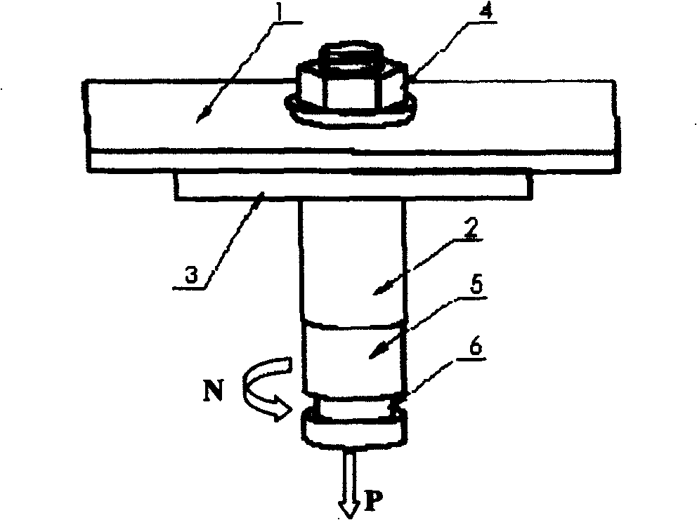
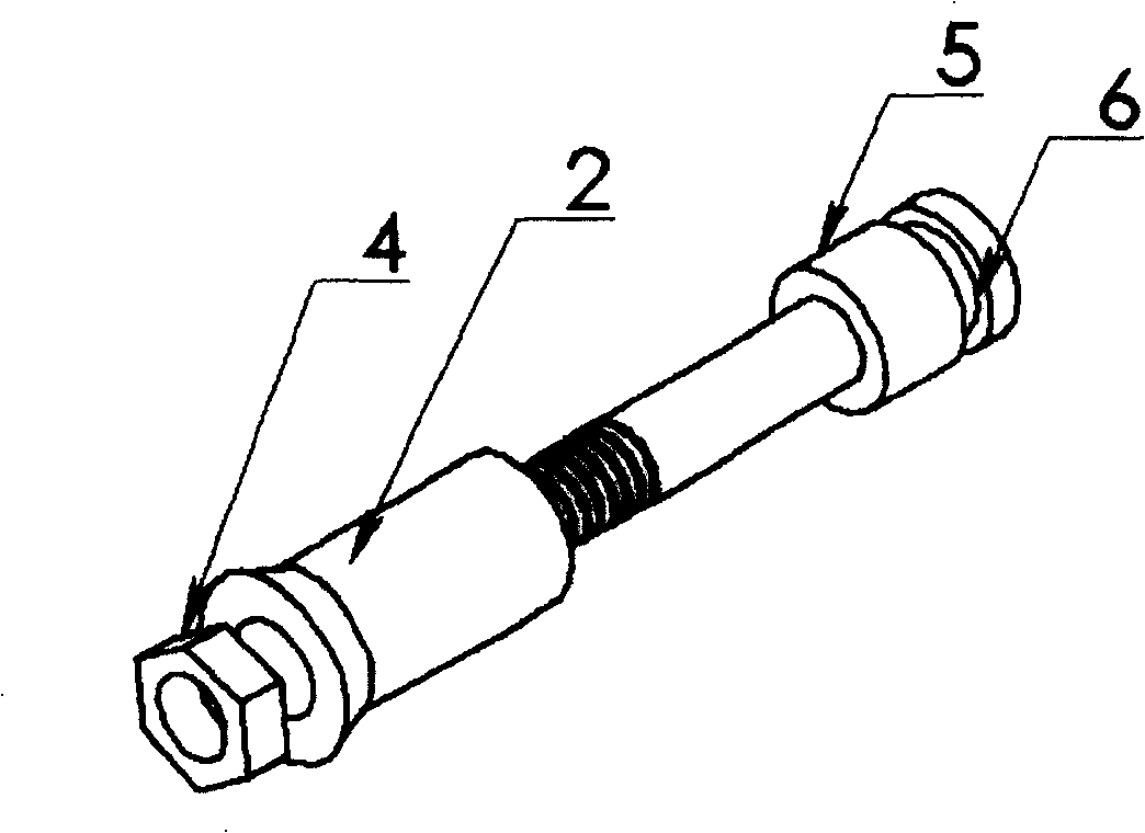
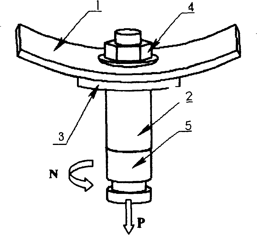
[0023] The present invention will be further described below in conjunction with accompanying drawing:

[0024] Such as figure 1 and figure 2 Shown is the first embodiment of the present invention. In the first stage, a hole is processed at the position of the pipe to be welded on the plate 1 to be welded. The shape of the hole is a factor that affects the quality of welding. The hole can be chamfered at full depth or It can be partly chamfered, and the angle of the chamfer can be 10°~30°. The inner diameter D1 of the hole is slightly larger than the outer diameter D2 of the pipe, which is convenient for the pipe to pass through the hole. One end of the pipe 2 should also be processed with a tapered surface. The value range of the angle is 10°~60°, and the outer diameter of the tube D2=12mm~50mm; a backing plate 3 is installed on the back of the wall plate 1; The mandrel 5 and the conduit 2 are fastened together with the nut 4 . The second stage is the friction heating sta...


PUM


Abstract

The invention relates to a pipe sheet friction welding method, and is characterized by simple process, high quality of welded joint and low residual stress. It is used for welding of aluminum alloy, magnesium alloy,copper and copper alloy and various magnesium alloy and steel.

Description

technical field [0001] The invention belongs to the field of welding, and in particular relates to a tube plate friction welding method. Background technique [0002] Friction welding is a pressure welding method, which uses the heat generated by the relative frictional motion and plastic flow between the contact surfaces of the weldment under the action of external force to make the contact surface and its adjacent metal reach viscoplasticity. state and produce appropriate macroscopic plastic deformation, and the welding is completed through mutual diffusion and dynamic recrystallization between the materials on both sides. [0003] At present, in various pressure vessels, such as aerospace storage tanks, various tubes are installed on the surface of the container due to various reasons. These tubes are usually welded by conventional fusion welding methods, such as manual arc welding, argon tungsten arc welding, etc. Welding, gas metal shielded welding, etc., the joint for...

Claims


Application Information

Patent Timeline
Patent Type & Authority Patents(China)
IPC IPC(8): B23K20/12B29C65/06
Inventor 王国庆陈浩刘宪力刘景铎杜岩峰
Owner CAPITAL AEROSPACE MACHINERY
Why Eureka
Try Eureka