Miniature efficient self-circulating electronic cooler

An electronic cooling and self-circulation technology, which is applied in the fields of electrical solid devices, cooling/ventilation/heating transformation, instruments, etc., can solve the problems of low heat flux density, low reliability, high operation and maintenance costs, etc.

Inactive Publication Date: 2008-10-01
GUANGZHOU INST OF ENERGY CONVERSION - CHINESE ACAD OF SCI
View PDF6 Cites 0 Cited by
  • Summary
  • Abstract
  • Description
  • Claims
  • Application Information

AI Technical Summary

Problems solved by technology

[0003] In electronic cooler products, typical traditional products such as radiators and fans can no longer meet the current cooling needs of electronic components. Therefore, electronic cooler products with micro heat pipes and capillary pump circuits have begun to appear.
The advantage of micro heat pipe and capillary pump circuit is that it belongs to passive cooling, but the heat flux that can be removed is still relatively low when using heat pipe and micro heat pipe technology to solve the heat dissipation problem of laptop computer CPU chips, communication base stations, and high-power electronic components.
The use of coolers that require mechanical components such as pumps and fans has disadvantages such as complicated equipment, low reliability, pipeline connectors, valves, etc., occupying a large volume of space, and high operation and maintenance costs.

Method used


Image

  • Miniature efficient self-circulating electronic cooler
  • Miniature efficient self-circulating electronic cooler
  • Miniature efficient self-circulating electronic cooler

Examples


Embodiment 1

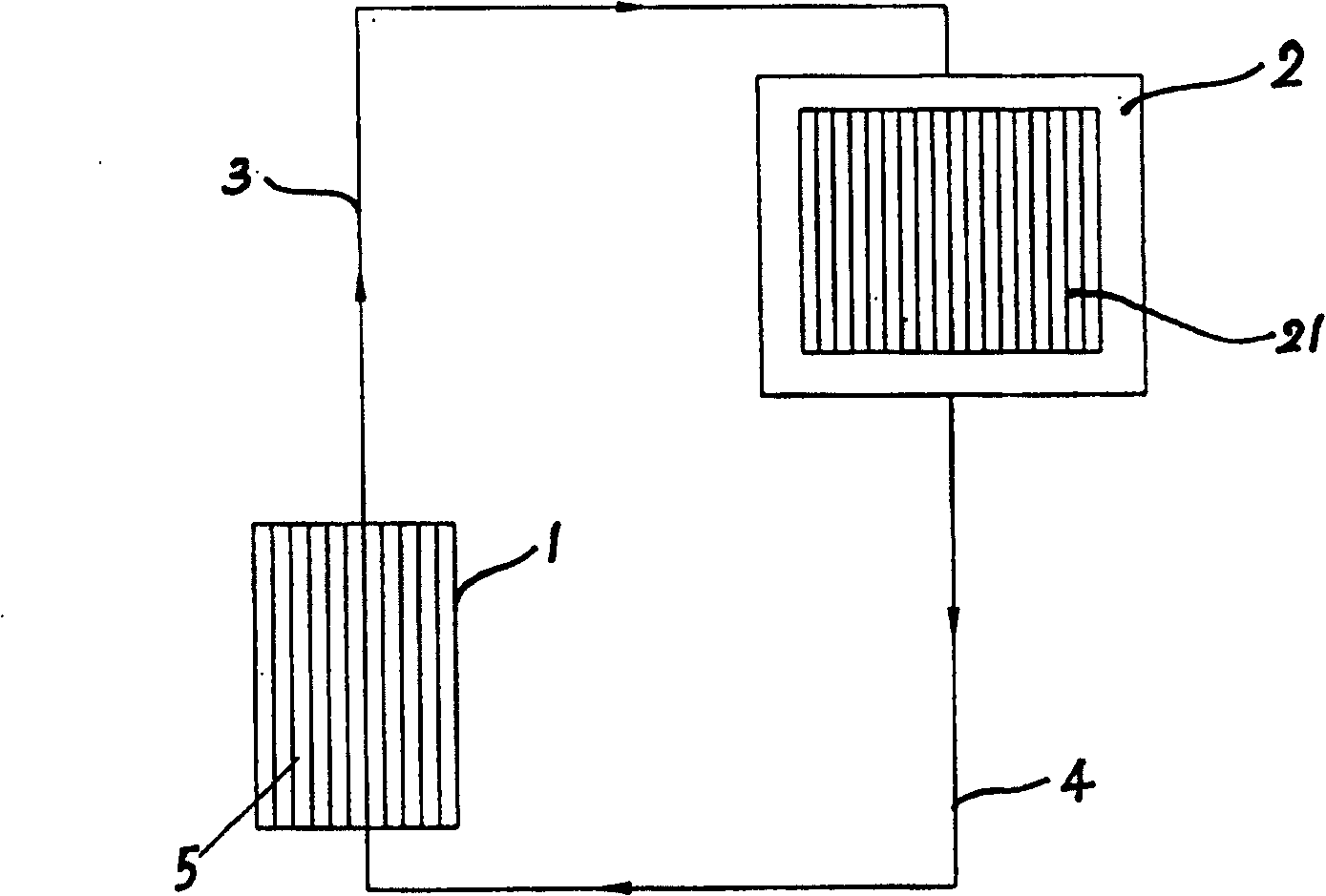
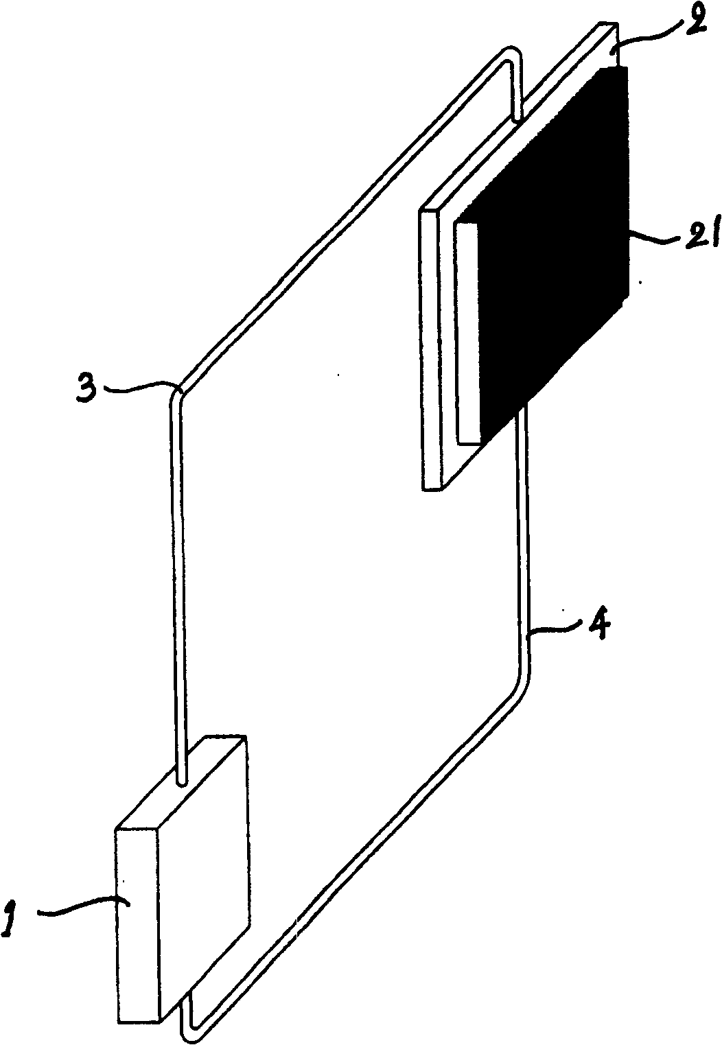
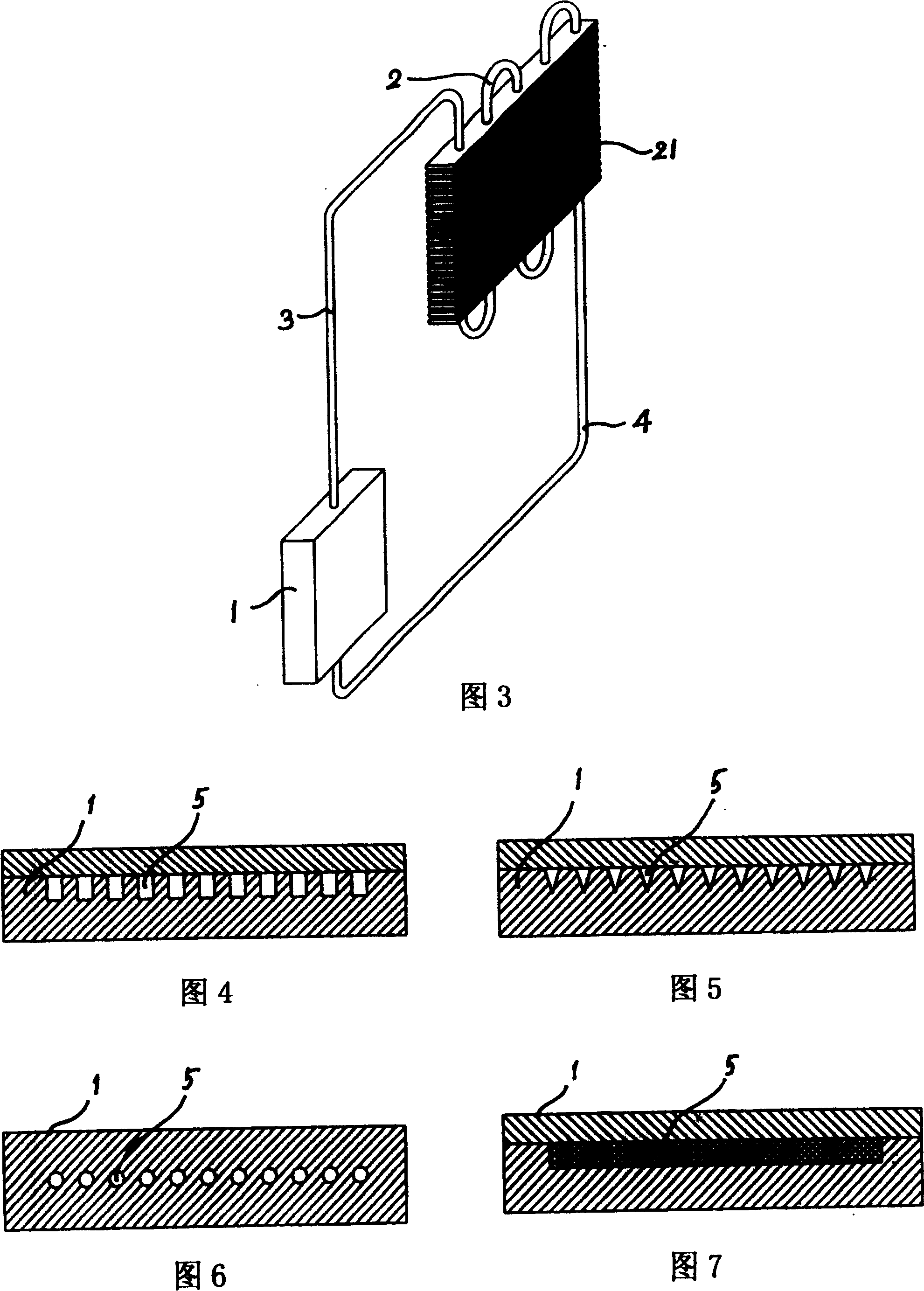
[0024] This miniature high-efficiency self-circulating electronic cooler such as figure 2 As shown, the microchannel evaporator 1, steam pipe 3, condenser 2 and liquid pipe 4 are connected in series in sequence to form a one-way circulation loop, wherein the microchannel evaporator 1 is processed on a copper plate base to process multiple parallel micro Groove is packaged with a copper plate on it, and the two ends are packaged with metal blocks and leave input and output ports, thereby forming the micro channel 5 in the micro channel evaporator 1, the cross section of said micro channel is square, as shown in Figure 4 As shown, the width and depth of the microchannels are within 3 mm. The cross-section of said micro channel can also be triangular or circular, as shown in Fig. 5 and Fig. 6 . The structural form of forming said microchannel can also be shown in Figure 7, that is, a porous medium is assembled in the copper plate base of microchannel evaporator 1 to form said m...

Embodiment 2

[0026] The miniature high-efficiency self-circulating electronic cooler is shown in Figure 3, and the microchannel evaporator 1, the steam pipe 3, the condenser 2 and the liquid pipe 4 are sequentially connected in series to form a one-way circulation loop. Wherein the structure of the microchannel evaporator 1 is basically the same as that of the first embodiment. The condenser 2 is a serpentine copper tube with cooling fins 21 installed on the outside. The condenser 2 is located above the microchannel evaporator 1, so that the liquid working fluid filled in the circuit can form a self-circulation in the circuit under the action of gravity.


PUM


Abstract

The electronic cooler comprises a micro channel evaporator and a condenser. The said micro channel evaporator possesses a metal base with high thermal coefficient, and micro channels are enclosed base seat arranged along region of the base plane. Micro channels of the evaporator through steam pipe and liquid pipe is connected to the condenser forming a one-way cycle loop in series. The micro channel evaporator is located in space position below the condenser, making working fluid cycle in loop. In the invented cooler, heat quantity of heating electronic component (chip) drives circular flow of working fluid in loop composed of micro channel evaporator, steam pipe, condenser and liquid pipe without need of rotational mechanical pump so as to provide features of compact structure, simple, no noise, small size, high thermal conduction, and good cost performance ratio.

Description

technical field [0001] The invention relates to a heat radiation cooling device for electronic components, in particular to a heat radiation cooling device for high heat flux density electronic components. Background technique [0002] In recent years, with the development of high-tech information industry, people are eager to speed up the research on "thermal management" technology. One of the reasons is that the integration degree of electronic circuits has been greatly improved, and the heat generation has increased. The second is that the high-tech industry is improving. At the same time of integration, advanced and compact electronic packaging technology is also being developed. The above two reasons have greatly improved the heat flux. [0003] In electronic cooler products, typical traditional products such as radiators and fans can no longer meet the current cooling needs of electronic components. Therefore, electronic cooler products with micro heat pipes and capill...

Claims


Application Information

Patent Timeline
Patent Type & Authority Patents(China)
IPC IPC(8): H01L23/427H05K7/20G06F1/20H01L23/473H01L23/34
Inventor 徐进良施慧烈
Owner GUANGZHOU INST OF ENERGY CONVERSION - CHINESE ACAD OF SCI
Why Eureka
Try Eureka