Measuring method for leakage of hydraulic system and its application

A technology of hydraulic system and measurement method, which is applied in the direction of liquid tightness measurement by using liquid/vacuum degree, and by measuring the increase and decrease rate of fluid, etc., which can solve the problems of poor versatility and cumbersome measurement methods, and achieve strong versatility and measurement The method is simple and fast, and the effect of reducing production and equipment maintenance costs

Inactive Publication Date: 2008-10-15
NINGBO BAOXIN STAINLESS STEEL
View PDF5 Cites 2 Cited by
  • Summary
  • Abstract
  • Description
  • Claims
  • Application Information

AI Technical Summary

Problems solved by technology

For a long time, internal leakage has been an important problem in the hydraulic system. It is like a black box for equipment maintenance personnel. It contains a lot of important information in the hydraulic system, but it is difficult to understand intuitively.
For this reason, scientific and technical personnel have researched and developed hydraulic system internal leakage measurement methods, such as the Chinese patent No. 95121774.7 "Detection method for hydraulic elevator oil leakage". The first step is to perform floor service operations when receiving a car call signal 1. Reset the timer to zero and measure the oil temperature; the second step is to increase the count value of the timer when the car stops at a certain floor and the door opening range switch does not deviate from the door opening range sensor plate; the third step is to measure the oil temperature and time Until the car deviates from the normal position; the fourth step is to measure the oil temperature when the count value of the timer is zero, the oil temperature when the door opening range switch deviates from the sensor plate, and the time when the car deviates from the normal position to the abnormal position; the fifth The first step is to compare the lowering amount of the car with the preset value; the sixth step is to judge the state of the elevator system; the defect is that the measurement method is cumbersome and the versatility is relatively poor. Due to the limitation of its elevator products, it cannot be carried out on other hydraulic systems. Promote application

Method used


Image

  • Measuring method for leakage of hydraulic system and its application
  • Measuring method for leakage of hydraulic system and its application
  • Measuring method for leakage of hydraulic system and its application

Examples


Embodiment Construction

[0032] The present invention will be further described in detail below in conjunction with the accompanying drawings and embodiments.

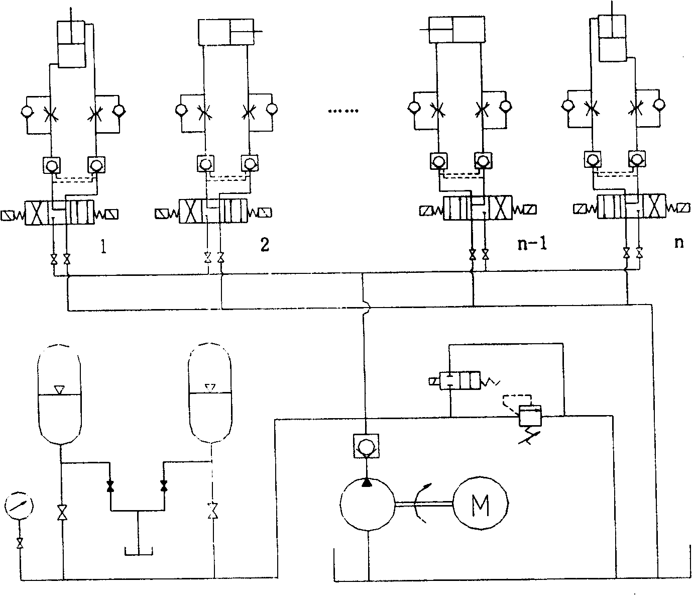
[0033] 1. Basic principles

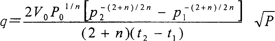
[0034] Under certain conditions, the accumulator is used as an independent oil supply source, the internal leakage is the only load, and the internal leakage orifice is regarded as a small orifice orifice. All internal leakage is directly leaked from the high-pressure chamber to the low-pressure chamber. Using the pressure oil provided by the accumulator and the internal leakage of the system to establish an equation, two basic algorithms for the internal leakage flow of the hydraulic system can be obtained: 1. The average value algorithm; 2. The calculation method of the small orifice throttling formula:

[0035] Q ‾ = ΔV ΔT = V 0 [ ...


PUM


Abstract

The invention is a method for measuring internal leakage of a hydraulic system, comprising the steps of: (1) using original hydraulic energy storage device at hydraulic station or on main pressure pipeline in the hydraulic system, or connecting special measuring hydraulic energy storage device into the system; (2) firstly measuring actual pre-charged gas pressure P0 of the energy storage device and able to obtain effective gas volume V0 according to specification of the energy storage device or actually measure it; (3) then letting the hydraulic system reach normal working pressure, stopping the system from do work to outside, turning off the working pump at the hydraulic station, letting the energy storage device singly supply oil to the system, and recording starting time t1, and initial pressure P1 as well as some middle time t2 and corresponding pressure value P2; (4) by formula, calculating internal leakage of the hydraulic system. And the method is simple and convenient and has strong universality.

Description

technical field [0001] The invention relates to a method for measuring internal leakage of a hydraulic system and its application. Background technique [0002] Hydraulic equipment is widely used in the machinery industry, especially in heavy industry. For a long time, internal leakage has been an important problem in the hydraulic system. It is like a black box for equipment maintenance personnel, which contains a lot of important information in the hydraulic system, but it is difficult to understand intuitively. For this reason, scientific and technical personnel have researched and developed hydraulic system internal leakage measurement methods, such as the Chinese patent No. 95121774.7 "Detection method for hydraulic elevator oil leakage". The first step is to perform floor service operations when receiving a car call signal 1. Reset the timer to zero and measure the oil temperature; the second step is to increase the count value of the timer when the car stops at a cer...

Claims


Application Information

Patent Timeline
Patent Type & Authority Patents(China)
IPC IPC(8): G01M3/26
Inventor 何荣志
Owner NINGBO BAOXIN STAINLESS STEEL
Why Eureka
Try Eureka