Method for raising constant-current source circuit performance

A constant current source and circuit technology, which is applied in the direction of adjusting electrical variables, control/regulation systems, instruments, etc., can solve the problems of reduced efficiency of constant current source circuits, difficulties in post-stage analog/digital conversion, and impact on final layout performance, etc. , to reduce the possibility of error or damage, improve load utilization, and avoid errors

Active Publication Date: 2008-11-12
SHANGHAI MICRO ELECTRONICS EQUIP (GRP) CO LTD
View PDF3 Cites 2 Cited by
  • Summary
  • Abstract
  • Description
  • Claims
  • Application Information

AI Technical Summary

Problems solved by technology

from figure 1 It can be clearly seen that the load voltage is based on the power supply Vcc as the reference terminal, and the voltage of the general power supply is above +12VDC, which brings great difficulties to the analog / digital conversion of the subsequent stage.
[0003] Under normal circumstances, the absolute voltage value of the analog input terminal of most A / D conversion devices is between +5V and +10V. If adding differential devices or other level shifting processing methods are used, on the one hand, it will bring errors to the entire measurement system. ; On the other hand, according to the characteristics of the differential device, if the input voltage up to +12VDC is to be differentially calculated, the power supply voltage of the differential device must be further increased, which is more difficult in actual use. It will affect the performance of the final layout, or reduce the input value by increasing the resistor Rext to divide the voltage, but this will cause the efficiency of the constant current source circuit to be greatly reduced

Method used


Image

  • Method for raising constant-current source circuit performance
  • Method for raising constant-current source circuit performance
  • Method for raising constant-current source circuit performance

Examples


Embodiment Construction

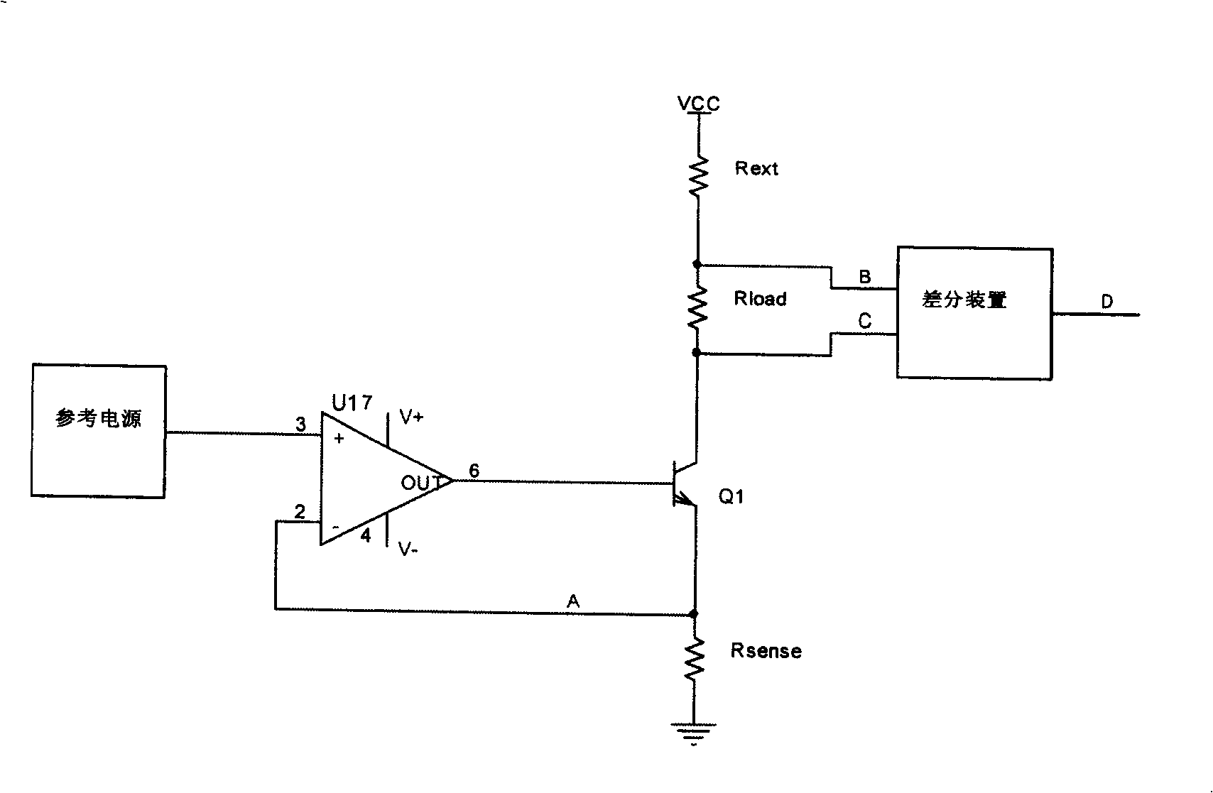
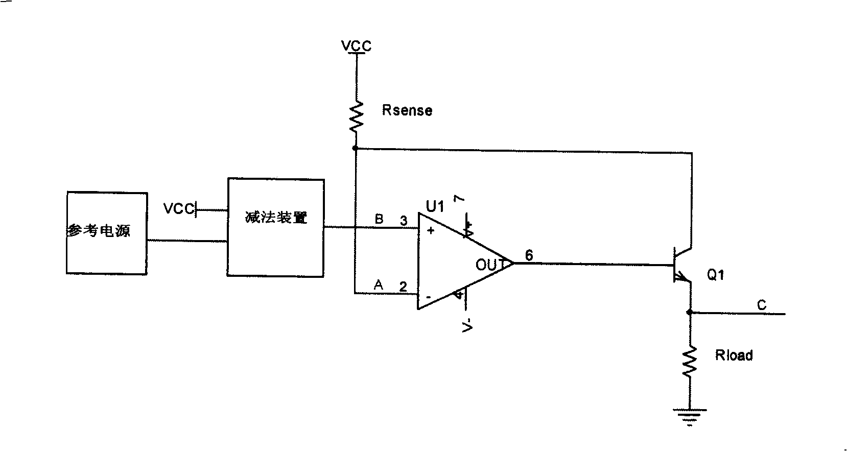
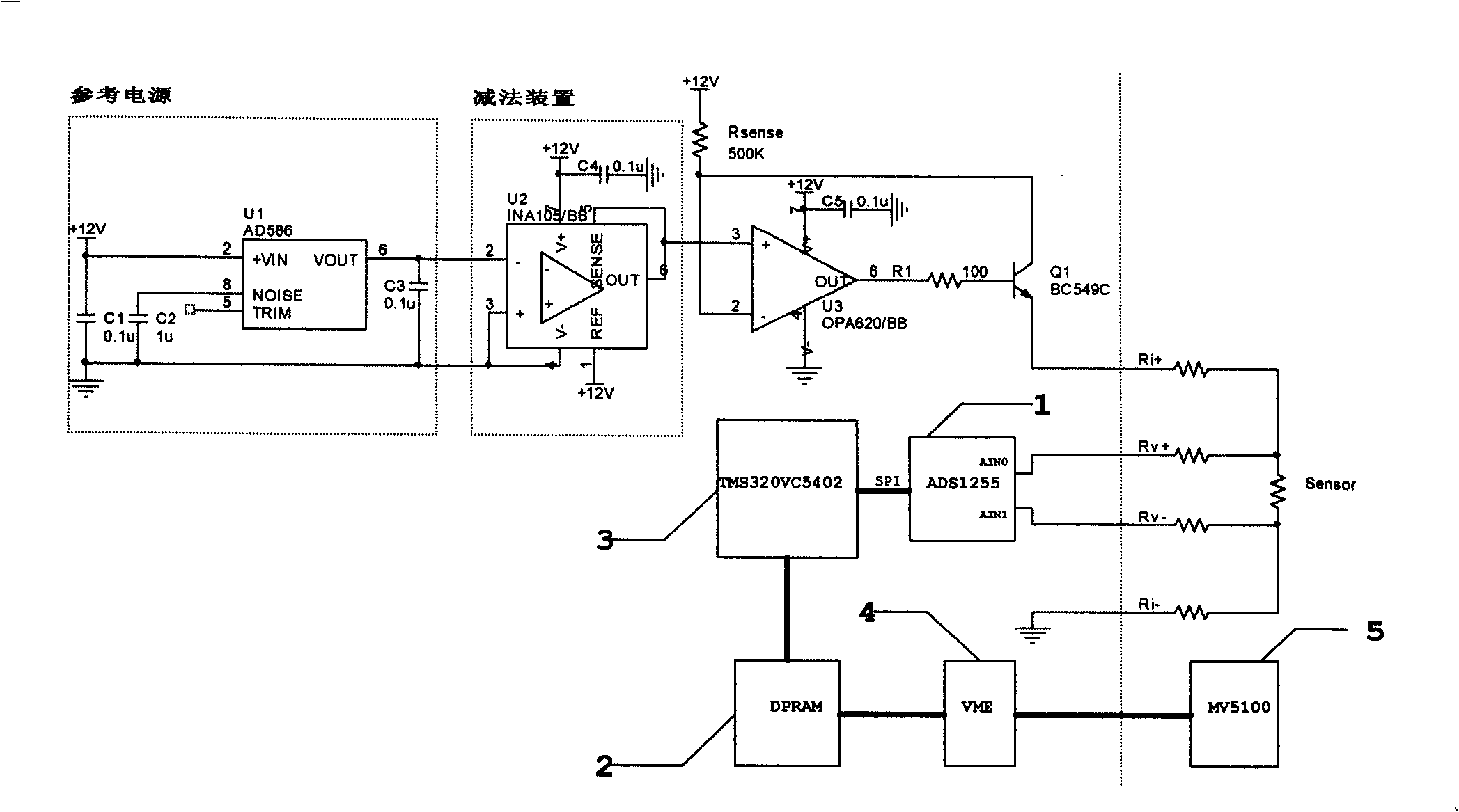
[0021] The constant current source circuit of the present invention is as figure 2 shown. by the reference voltage V ref Add the subtraction device on and feed it to the voltage at the positive input of the op amp: V A =(V CC -V ref ). According to the principle of operational amplifier, it can be seen that the voltage at point B is equal to the voltage at point A: V B =V A =(V CC -V ref ). Reference resistor R sense Voltage on both sides: , has nothing to do with the power supply Vcc.

[0022] According to Ohm's law, the reference resistor R sense The current on I sense =V sense / R sense =V ref / R sense . According to the current characteristics of the triode, the current flowing through both sides of the load can be known:

[0023] I load = I e =(I c -I b )=(I c -I c / β)=(1-1 / β)I c =(1-1 / β)I sense =(1-1 / β)V ref / R sense , and the current amplification factor of the general triode β=(150~250), so I load ≈V ref / R sense , when V ref and R se...


PUM


Abstract

The invention provides a method to improve the constant-current source circuit performance. The subtraction device is set between the reference supply and the operational amplifier. The result subtracted from the circuit current source Vcc and the reference supply is as the positive input end of the operational amplifier and the reference resistance is connected between the circuit current source Vcc and the negative input end of the operational amplifier which the output end is connected to the base of the NPN triode and the collector electrode is connected to the negative input of the operational amplifier, the charge is connected between the emitter of the triode and the current source ground. The zero potential is the reference point for the voltage of the charge to decrease the dependence of the constant-current source circuit to the current source, so it can improve the loading and anti-interference performance of the circuit.

Description

technical field [0001] The invention relates to a constant current source circuit and relates to a method for improving the performance of the constant current source circuit. Background technique [0002] Currently, if figure 1 The constant current source circuit of the shown principle has been widely used, and its detailed description can be found in Figure 17 in National Semiconductor Application Note20 "An Applications Guide for Op Amps". From figure 1 It can be clearly seen that the load voltage is based on the power supply Vcc as the reference terminal, and the voltage of the general power supply is above +12VDC, which brings great difficulties to the analog / digital conversion of the subsequent stage. [0003] Under normal circumstances, the absolute voltage value of the analog input terminal of most A / D conversion devices is between +5V and +10V. If adding differential devices or other level shifting processing methods are used, on the one hand, it will bring errors...

Claims


Application Information

Patent Timeline
Patent Type & Authority Patents(China)
IPC IPC(8): G05F1/46
Inventor 常依斌汤勇李小平束剑平
Owner SHANGHAI MICRO ELECTRONICS EQUIP (GRP) CO LTD
Why Eureka
Try Eureka