External control type fan coupling device

An external control and coupling device technology, applied in pump devices, clutches, fluid clutches, etc., can solve the problems that the size and weight of the fan coupling device cannot be reduced, the size and weight of the electromagnet are increased, and the flexibility of valve components is reduced. The effect of improving suction efficiency, reducing size and weight, and reducing energy consumption

Inactive Publication Date: 2008-11-19
USUI KOKUSAI SANGYO KAISHA LTD
View PDF6 Cites 1 Cited by
  • Summary
  • Abstract
  • Description
  • Claims
  • Application Information

AI Technical Summary

Problems solved by technology

In addition, the following problems arise: the size and weight of the electromagnet increase; the size and weight of the fan coupling cannot be reduced; and more power consumption is required
In addition, if the armature is located at a position spaced from the rotating shaft in the oil tank, there is also the following disadvantage: when the fan rotates, because the armature is always in the oil, due to the resistance of the oil, the role of the armature, which is to open / close the valve Reduced flexibility of components

Method used


Image

  • External control type fan coupling device
  • External control type fan coupling device
  • External control type fan coupling device

Examples


Embodiment Construction

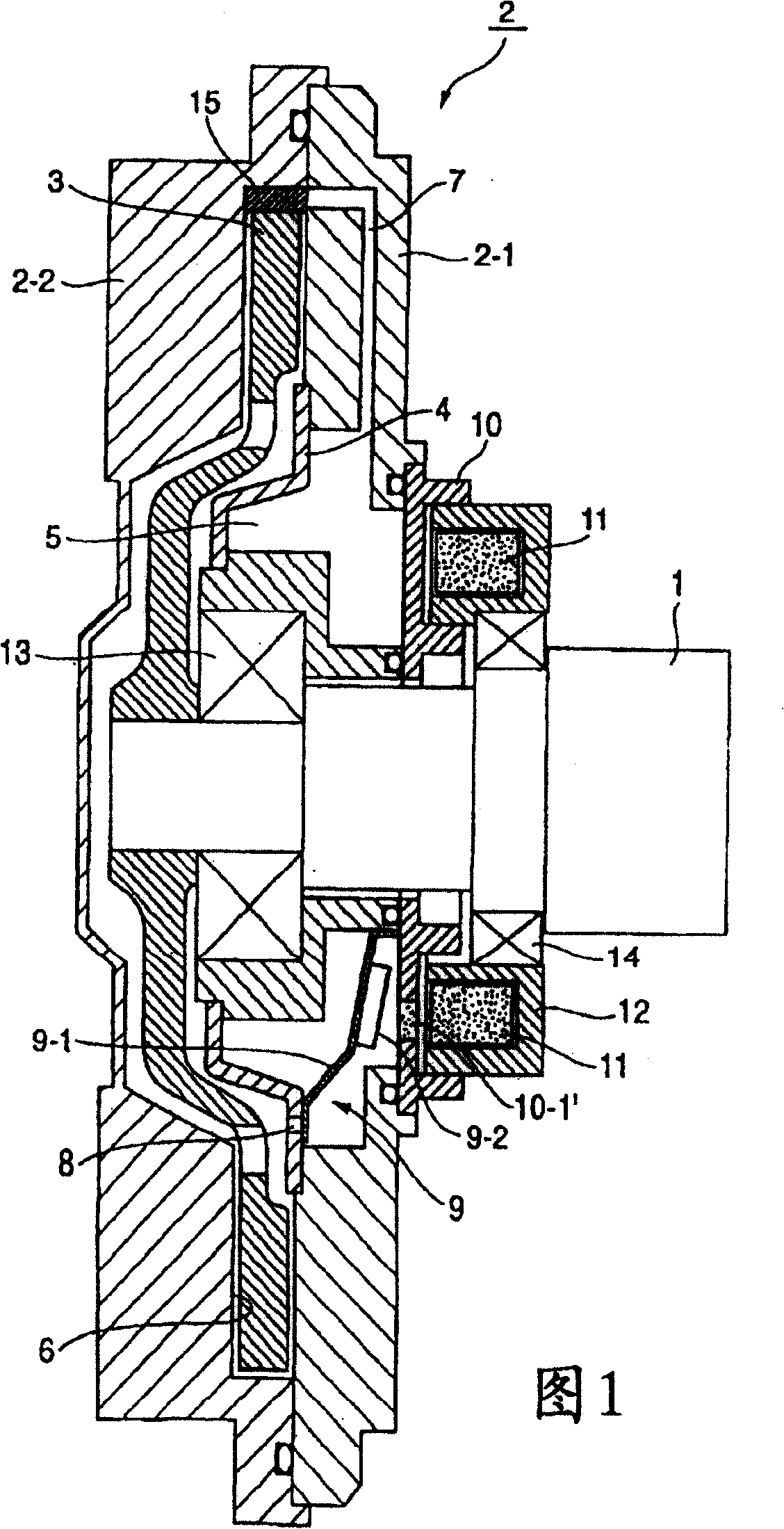
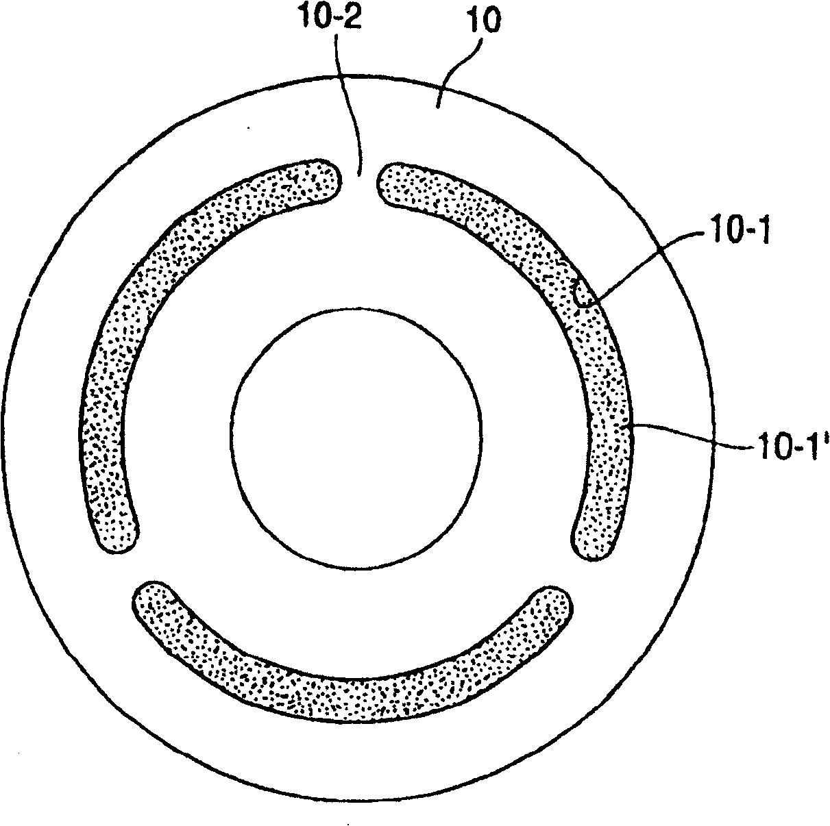
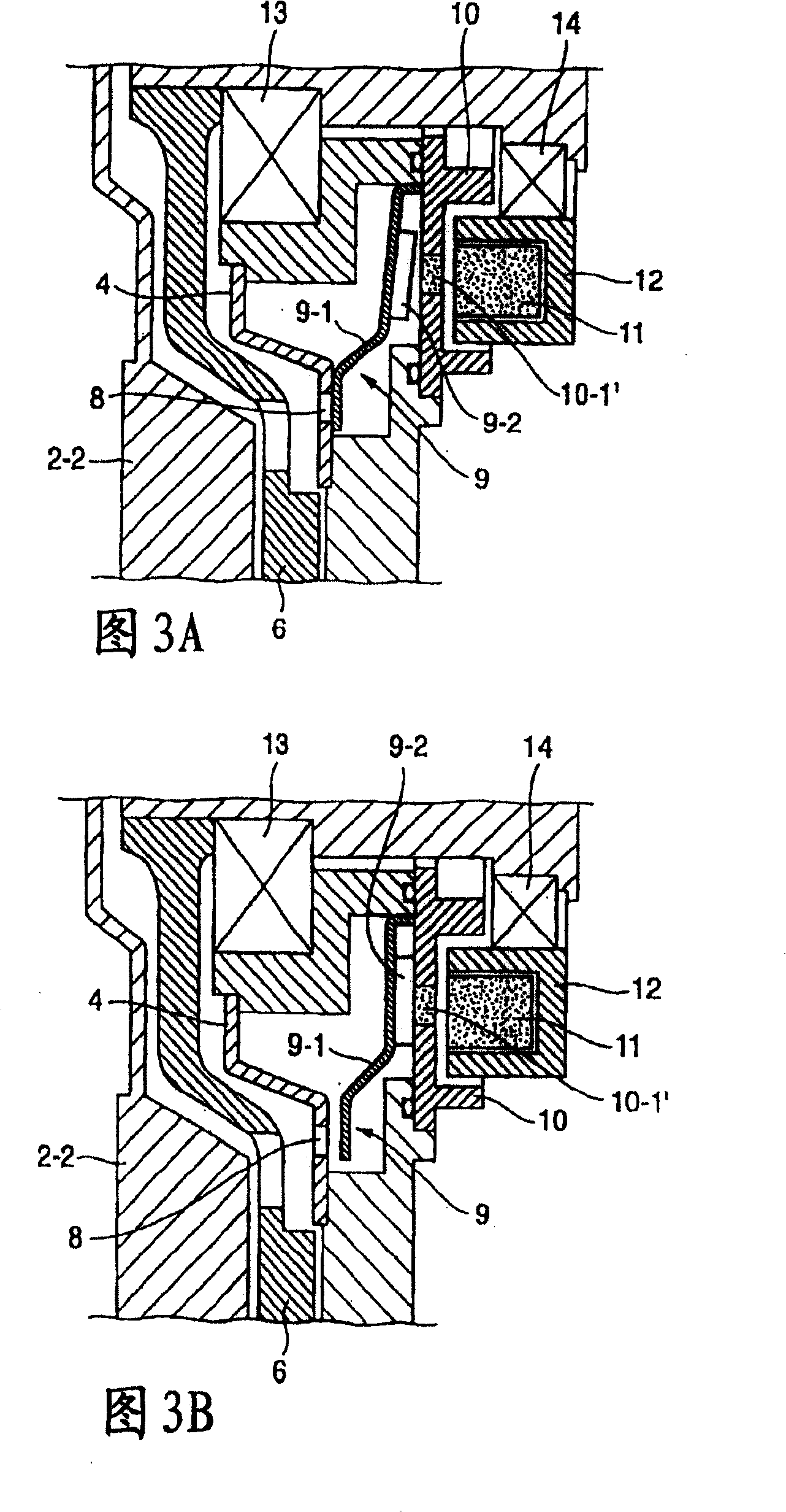
[0020] In Figure 1 to Figure 9 Among them, the number 1 indicates the rotating shaft (or drive shaft); the number 2 indicates the sealed shell; the number 2-1 indicates the shell; the number 2-2 indicates the cover; the number 3 indicates the drive plate; Oil tank; number 6 indicates torque transmission cavity; number 7 indicates oil recovery circulation channel; number 8 indicates oil supply adjustment hole; number 9 indicates oil supply valve parts; number 9-1 indicates leaf spring; number 9-2 indicates armature; number 10 Indicates a disc-shaped magnetic coil element (or magnetic component) having an annular portion and an arc-shaped slot; numerals 20 and 30 indicate annular magnetic coil elements (or magnetic components); numeral 40 indicates a non-annular magnetic coil element (or magnetic component); Numeral 11 denotes an electromagnet; Numeral 12 denotes an electromagnet support; Numerals 13 and 14 denote bearings; Numeral 15 denotes a baffle.

[0021] In the external...


PUM


Abstract

To reduce the size / weight and the power consumption of a fan-coupling device and to provide an external control type fan-coupling device intended to improve a fan rotation controllability. A fan-coupling device, in which the inside of a sealed housing borne on a rotary shaft fixing a drive disk thereon is divided by a partition into an oil sump and a torque transmission chamber housing the drive disc, so that the drive torque may be transmitted to a driven side with the oil fed into the torque transmission chamber and so that the communication passage of oil may be opened / closed and controlled by a valve member to be activated by an electromagnet. In the fan-coupling device, a magnetic member of either an integral structure or a split structure composed of a plurality of parts and assembled integrally is arranged between the electromagnet and the valve member (or armature), and the magnetic member is so assembled in the sealed housing that the magnetic flux of the electromagnet may be transmitted through the magnetic member to the armature.

Description

technical field [0001] The present invention generally relates to an externally controlled fan coupling in which the rotation of a cooling fan for an engine in an automobile or the like is controlled in response to changes in ambient temperature and changes in the operating conditions of the engine or the like. Background technique [0002] In the prior art, there is such a fan coupling device, in which the sealed housing includes a housing and a cover, and its interior is divided into an oil groove and a torque transmission chamber in which the drive disc is accommodated by a partition with an oil supply adjustment hole, wherein the baffle Formed in a portion of the inner peripheral wall surface facing the seal housing side of the outer peripheral wall portion of the drive plate, in which portion oil accumulates during rotation, an oil circulation passage is formed therein to lead to the stopper between the torque transmission chamber and the oil groove. plate, and set a va...

Claims


Application Information

Patent Timeline
Patent Type & Authority Patents(China)
IPC IPC(8): F16D35/00F04D25/00
Inventor 盐崎贤饭田吉信
Owner USUI KOKUSAI SANGYO KAISHA LTD
Why Eureka
Try Eureka