Integrated inrush current limiter circuit and method

A technology of a limiter circuit and inrush current, applied in circuit devices, emergency protection circuit devices for limiting overcurrent/overvoltage, emergency protection circuit devices, etc., can solve the problem of increasing the manufacturing cost of circuit cards, circuit cards and components Manufacturers struggle to benefit from issues such as economies of scale

Inactive Publication Date: 2008-11-26
SEMICON COMPONENTS IND LLC
View PDF4 Cites 0 Cited by
  • Summary
  • Abstract
  • Description
  • Claims
  • Application Information

AI Technical Summary

Problems solved by technology

Special design increases the manufacturing cost of the circuit card and requires inventory of different components, which makes it difficult for the manufacturers of circuit cards and components to benefit from economies of scale

Method used


Image

  • Integrated inrush current limiter circuit and method
  • Integrated inrush current limiter circuit and method
  • Integrated inrush current limiter circuit and method

Examples


Embodiment Construction

[0012] In the figures, elements with the same reference number have the same function.

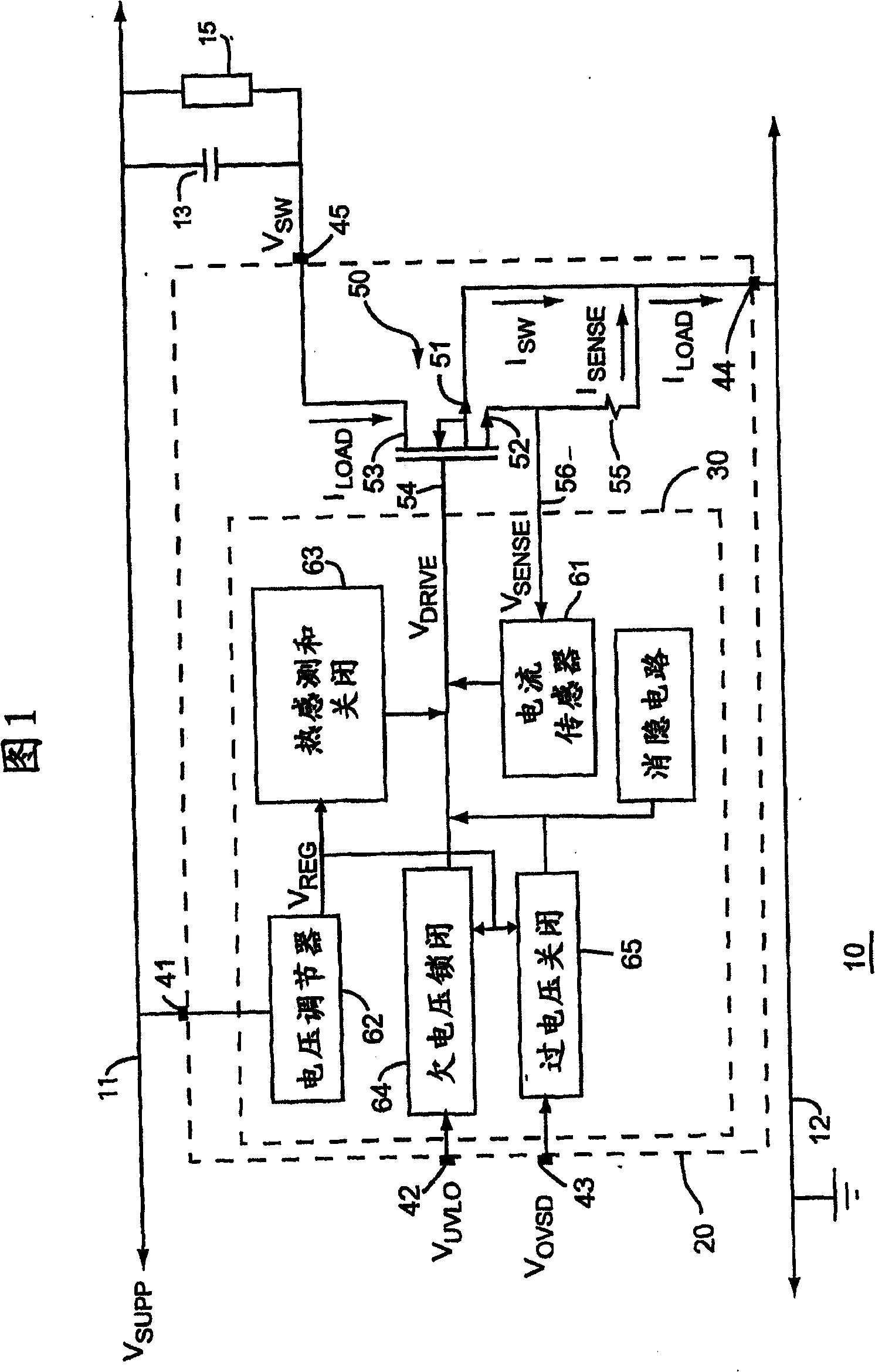
[0013] FIG. 1 is a simplified schematic diagram of a hot swappable circuit card 10, the circuit card 10 is used to be inserted into a SUPP = 48.0 Volts and / or unplugged from the distribution power bus 11 between the ground node 12. The power bus 11 and the ground node 12 can simultaneously provide power to other components (not shown) of the electronic system.

[0014] A large filter capacitor 13 smoothes out noise spikes on the power bus 11 to provide a stable bias voltage. The circuit performing the function of the circuit card 10 is represented as a load 15 which draws a load current I from the power bus 11 through an inrush current limiter circuit 20 LOAD . In one embodiment, load 15 includes a voltage regulator that obtains I LOAD = 10.0 amps of load current as a peak through capacitor 13 and load 15 . I LOAD A typical average is about 4 amps. In one embodiment, capacitor 13 ha...


PUM


Abstract

An inrush current limiter circuit (20) includes a mirrored transistor (50) responsive to a control signal (VDRIVE) developed from a sense current (ISENSE), and has a first source (51) coupled to a supply voltage, a common drain (53) that routes a load current (ILOAD) to an output node (45), and a second source that samples the load current to produce the sense current. A fault protection circuit (64) disables the mirrored transistor in response to a first fault condition (TEMP, UVLO) and is coupled to a first lead (43) for externally adjusting a fault threshold. A fault communication circuit (250) is coupled to the first lead to receive a fault signal representative of an external fault condition to disable the mirrored transistor.

Description

technical field [0001] The present invention relates generally to semiconductor devices, and more particularly to high current semiconductor devices for limiting current surges on a power supply bus. Background technique [0002] Many electronic systems are designed to allow users to insert or remove circuit cards without powering down the entire system, commonly referred to as "hot swapping". In systems that distribute power to multiple cards on the power bus, each circuit card typically includes large filter capacitors to reduce noise on the bus, so hot swapping can create inrush current spikes that, if left unchecked, It can reach hundreds of amps and can destroy a circuit card, its connector, or other circuit cards plugged into the system. Inrush current spikes can also cause data loss or other system failures to hot swapped cards or other system cards. To control the damaging effects of inrush current, hot-swappable circuit cards are configured with inrush current lim...

Claims


Application Information

Patent Timeline
Patent Type & Authority Patents(China)
IPC IPC(8): H02H9/00H02H3/00
CPCH02H3/006H02H9/001H02H9/02H02H9/00
Inventor 阿兰·R·巴尔
Owner SEMICON COMPONENTS IND LLC
Why Eureka
Try Eureka