Flip chip mounting method and flip chip mounting element
A mounting method and flip-chip technology, applied in the manufacturing of electrical components, electric solid-state devices, semiconductor/solid-state devices, etc., can solve the problems of difficult mounting procedures, difficult conduction states, productivity or reliability residues, etc., and achieve high productivity. Effect
- Summary
- Abstract
- Description
- Claims
- Application Information
AI Technical Summary
Problems solved by technology
Method used
Image
Examples
Embodiment approach 1
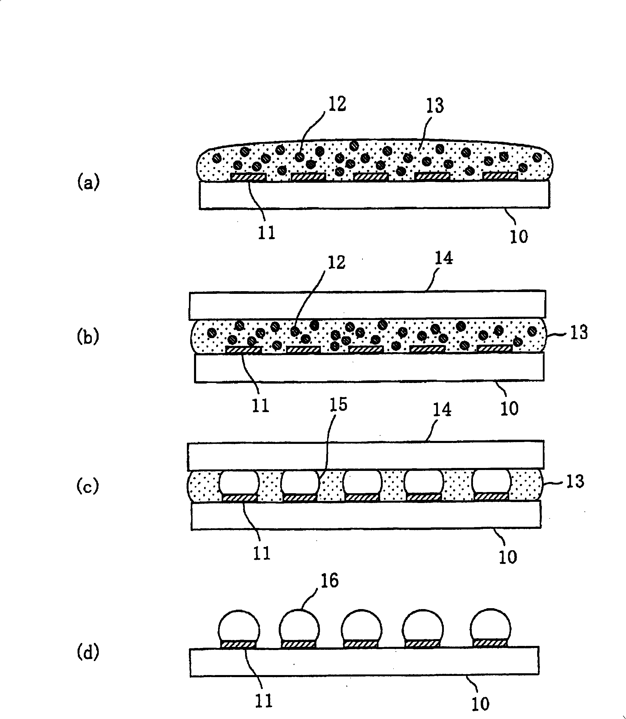
[0067] refer to figure 1 (a) to (d) describe a method of forming solder bumps in the other flip chip mounting method. like figure 1 As shown in (a), a resin 13 containing solder powder (not shown) and a convective additive 12 is supplied on a wiring board 10 on which a plurality of electrodes 11 are formed. Next, if figure 1 As shown in (b), while bringing the flat plate 14 into contact with the surface of the resin 13 supplied onto the wiring board 10, the wiring board 10 is heated to a temperature at which solder powder melts. In this heating process, the molten solder powder self-assembles, such as figure 1 As shown in (c), the grown solder balls 15 are selectively formed on the plurality of electrodes 11 . Then, if figure 1 As shown in (d), when the flat plate 14 is separated from the surface of the resin 13 and the resin 13 is removed, a wiring board 10 in which bumps 16 are formed on a plurality of electrodes 11 is obtained.
[0068] This bump forming method is cha...
Embodiment approach 2
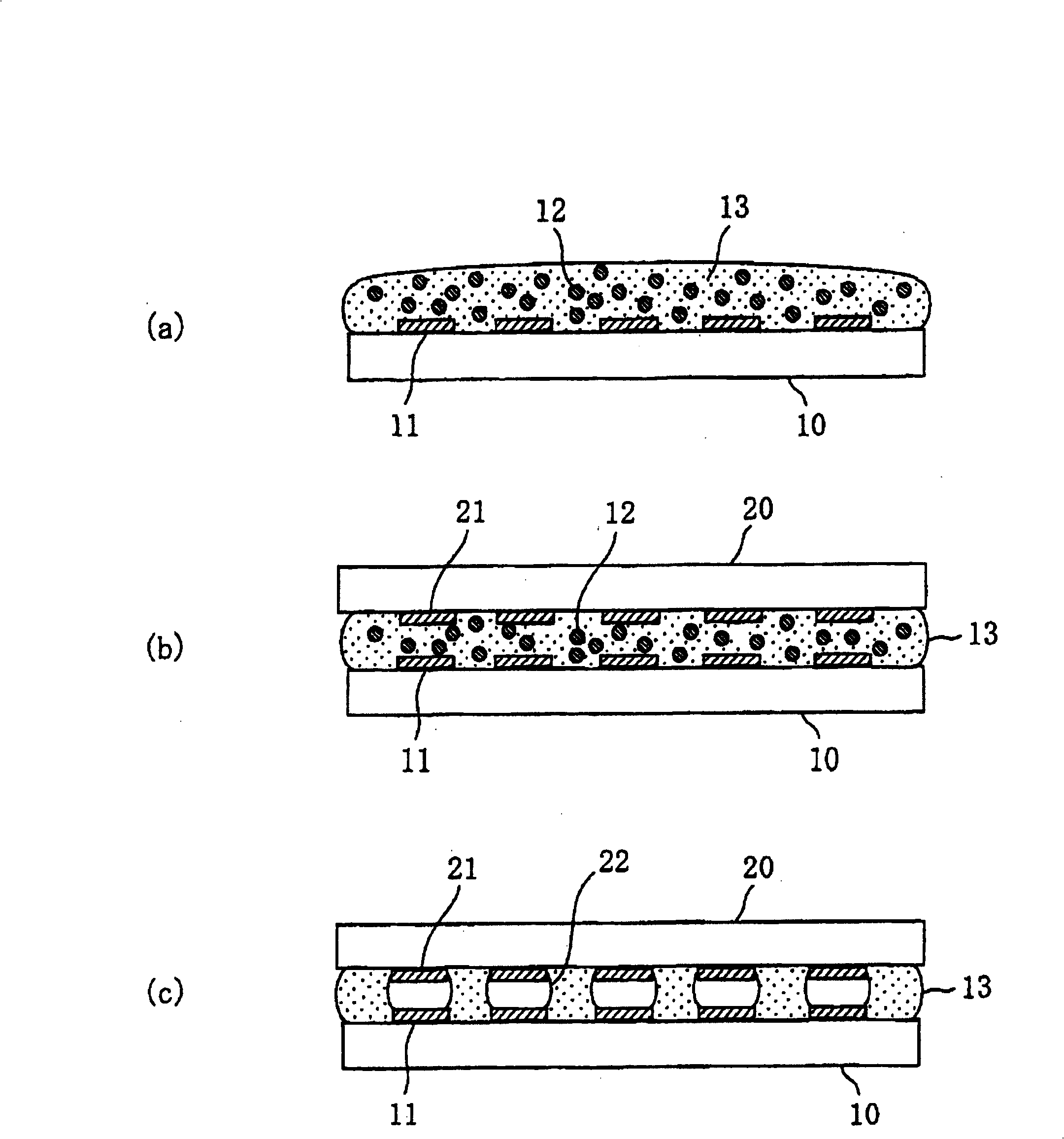
[0093] figure 2 (a) to (c) are diagrams showing basic steps of the flip chip mounting method according to Embodiment 2 of the present invention.
[0094] First, if figure 2 As shown in (a), a resin 13 containing solder powder (not shown) and a convective additive 12 is supplied on a wiring board 10 having a plurality of electrode terminals 11 . Next, if figure 2 As shown in (b), the semiconductor chip 20 is brought into contact with the surface of the resin 13 supplied on the wiring board 10 . At this time, the semiconductor chip 20 having a plurality of connection terminals 21 is arranged to face the wiring substrate 10 having a plurality of electrode terminals 11 . Then, in this state, wiring substrate 10 is heated to a temperature at which the solder powder melts or higher. Here, the heating temperature of the wiring board 10 is performed at the boiling point of the convection additive 12 or higher, and the boiling convection additive 12 convects in the resin 13 .
...
Embodiment approach 3
[0137] Hereinafter, Embodiment 3, which is various modifications of Embodiment 2, will be described with reference to the drawings.
[0138] Image 6 (a) and (b) are diagrams showing a structure when a plurality of semiconductor chips (20a, 20b, 20c, 20d) are mounted on the wiring board 10, Image 6 (a) represents its top view, Image 6 (b) means along Image 6 (a) Cross-sectional view of line B-B'.
[0139] Flip-chip mounting of a plurality of semiconductor chips (20a, 20b, 20c, 20d) on the wiring board 10 is performed by the following method.
[0140] First, a resin containing solder powder and a convective additive is preliminarily applied to regions on the wiring board 10 where the respective semiconductor chips (20a, 20b, 20c, 20d) are mounted. Then, each semiconductor chip is brought into contact with the resin surface so that the connection terminals of the respective semiconductor chips face the respective electrode terminals on the wiring substrate 10 . Then, the...
PUM
 Abstract
Description
Claims
Application Information
 - R&D
- Intellectual Property
- Life Sciences
- Materials
- Tech Scout
- Unparalleled Data Quality
- Higher Quality Content
- 60% Fewer Hallucinations
Browse by: Latest US Patents, China's latest patents, Technical Efficacy Thesaurus, Application Domain, Technology Topic, Popular Technical Reports.
© 2025 PatSnap. All rights reserved.Legal|Privacy policy|Modern Slavery Act Transparency Statement|Sitemap|About US| Contact US: help@patsnap.com


