
Vibration welding technology

A technology of vibration welding and welding parts, applied in welding equipment, welding equipment, welding accessories, etc., can solve the problems of affecting the welding progress, increasing labor intensity, difficult amplitude, etc., achieving good welding effect, convenient welding operation, The effect of improving welding speed and efficiency

Inactive Publication Date: 2009-02-04
黎凡七
View PDF5 Cites 0 Cited by
  • Summary
  • Abstract
  • Description
  • Claims
  • Application Information

AI Technical Summary

Problems solved by technology

[0003] However, in the vibration welding process of the prior art, the amplitude is controlled by adjusting the frequency. When the quality of the exciter is constant, it is difficult to obtain a predetermined amplitude by adjusting the frequency for large welded components; This process uses multiple sensors and converts them one by one to pick up vibrations, which will not only increase the equipment cost and sensor maintenance workload, but also have such difficulties in actual operation, that is, for components with criss-cross welds, the welds have some Distributed on the outer surface of the component, and some on the inner surface, the welding operator sometimes stands, sometimes pedals on the upper part of the component, and sometimes needs to enter the inner cavity of the component, so that the operator must frequently travel to and from the control panel far away from the component (to toggle sensor changeover switch) and the component, not only affects the welding progress, but also increases the labor intensity because the operator jumps up and down on the component too much, drills out and drills, and is extremely inconvenient

Method used


Image

  • Vibration welding technology
  • Vibration welding technology
  • Vibration welding technology

Examples


Embodiment Construction

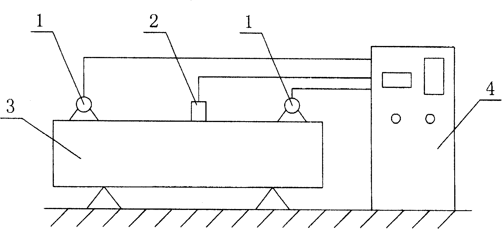
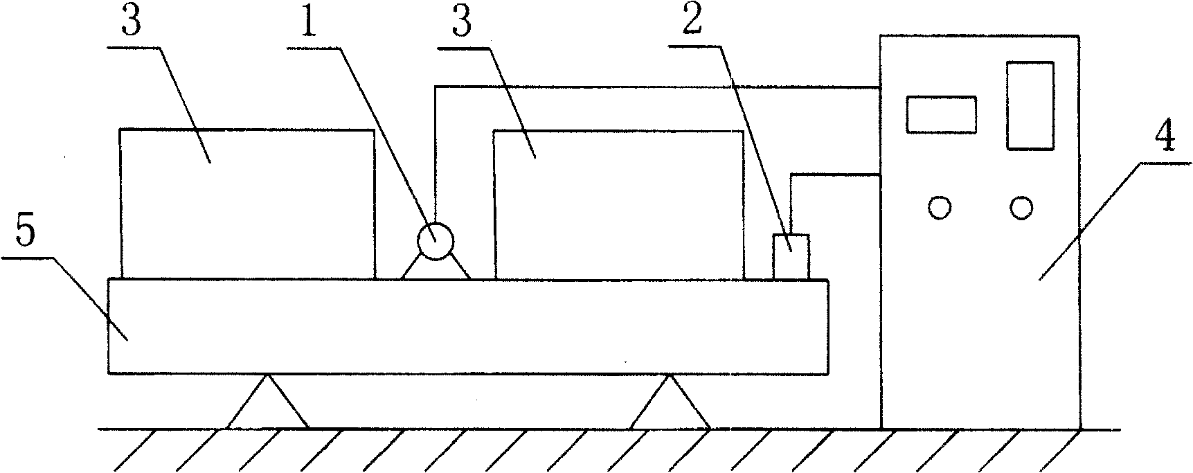
[0040] 1. After the welded components are assembled and welded according to the welding process, they are supported stably with rubber or wood. The support method varies according to different types of components.

[0041] a. For beam-shaped members, the support position is 2 / 9L from both ends of the weldment (L is the length of the weldment), and the exciter is fixed at the center or one side of the center or at the end.

[0042] b. For circular workpieces, support them at four or three points, and the vibrator is fixed between two points.

[0043] c. For plate-shaped workpieces, the support is arranged along the length direction, the fulcrum is 1 / 3L or 2 / 3L away from the end, and the exciter is clamped at the middle position.

[0044] d. For welded components with a ratio of length, width, and height close to 1, select a place with low rigidity in the three directions to support four points, the fulcrum is 1 / 3L or 2 / 3L from the end, and the exciter is fixed on both sides or ...


PUM


Abstract

The vibration welding technology of the present invention includes: 1. connecting a vibration exciter rigidly to the welded part or a vibration table with the welded part, and regulating the exciting force of the vibration exciter in resonant state to make the welded part obtain required amplitude; 2. maintaining the welded part in resonant state and in stable amplitude; 3. selecting one relatively low work frequency in resonant state and with amplitude not greater than one third of the resonant amplitude; 4. picking up the vibration with one acceleration sensor fixed in certain distance to the welding seam and shifting with the welder for tracking and monitoring the vibration parameters; etc. The present invention has convenient welding operation, high welding effect and high welding speed, and is suitable for welding different kinds of member.

Description

technical field [0001] The present invention relates to welding technology, and further refers to improved vibration welding technology. Background technique [0002] Vibration welding refers to a welding method in which the workpiece is vibrated while welding in the process of welding steel parts. This method can eliminate the internal stress of the welding layer and the welding deformation and cracks (hidden cracks) produced during the welding process, reduce slag pores and pores, increase more and healthier effective crystallization nuclei in the weld pool, refine the grains, Prevent jump welding, improve welding quality and material mechanical properties and fatigue life. [0003] However, in the vibration welding process of the prior art, the amplitude is controlled by adjusting the frequency. When the quality of the exciter is constant, it is difficult to obtain a predetermined amplitude by adjusting the frequency for large welded components; This process uses multip...

Claims


Application Information

Patent Timeline
Patent Type & Authority Patents(China)
IPC IPC(8): B23K37/00B23K9/32B23K9/095
Inventor 黎凡七
Owner 黎凡七
Learn More