Compositions, methods and devices for high temperature lead-free solder

A composition, solder technology, applied in the direction of electrical components, welding/cutting media/materials, welding equipment, etc., can solve problems such as poor mechanical properties

Inactive Publication Date: 2009-04-08
HONEYWELL INT INC
View PDF12 Cites 11 Cited by
  • Summary
  • Abstract
  • Description
  • Claims
  • Application Information

AI Technical Summary

Problems solved by technology

But the solidus line of J alloy is 228 ℃, and its mechanical properties are also poor

Method used

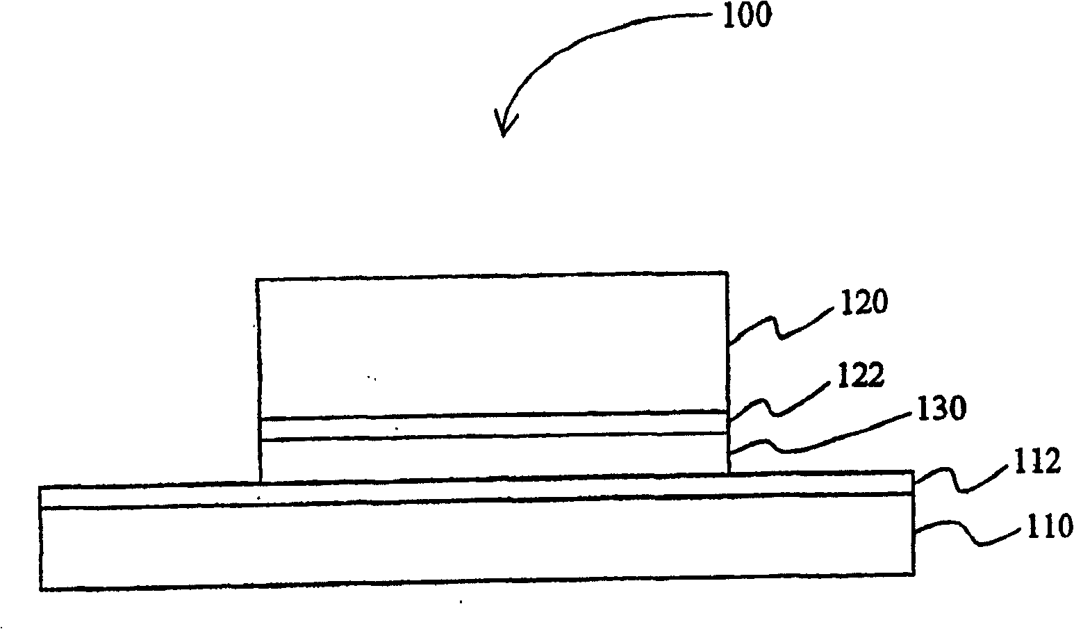

Image

  • Compositions, methods and devices for high temperature lead-free solder

Examples


Embodiment Construction

[0027] Solder joints are often subjected to shear loads due to differences in the coefficients of thermal expansion of different materials. Therefore, alloys joining these materials are particularly required to have low shear modulus and thus good resistance to thermomechanical fatigue. For example, low shear modulus and good thermal-mechanical fatigue resistance help avoid chip cracking when mounting chips, especially when relatively large chips are bonded to a solid support.

[0028] Based on the known modulus of elasticity of pure metals, Ag and Bi show some solid-state mutual solubility and the Ag-Bi system does not contain intermetallic phases or intermediate phases, the Ag-Bi alloy of the present invention is stable at room temperature The shear modulus is in the range of 13-16 GPa (assuming that the shear modulus at room temperature is an additive property - ie the mixture rule described below). The 13-16GPa range of the shear modulus at room temperature of the alloy i...


PUM

PropertyMeasurementUnit
shear modulusaaaaaaaaaa

Abstract

A lead-free solder (130) comprises an alloy that includes Ag in an amount of 2 wt % to 18 wt %, Bi in an amount of 98 wt % to 82 wt %, and a third element in an amount of 0.1 wt % to 5.0 wt %. The third element is selected from the group consisting of Au, Cu, Pt, Sb, Zn, In, Sn, Ni and Ge. Contemplated alloys have a solidus of no lower than 230°C and a liquidus of no higher than 400°C.

Description

technical field [0001] The invention relates to the field of lead-free solder. Background technique [0002] Most known die connection methods use high-lead solder to connect the semiconductor chip in the integrated circuit to the lead frame to form a mechanical connection and enable thermal and electrical conduction between the chip and the lead frame. Although most high-lead solders are relatively inexpensive and exhibit a variety of good physical and chemical properties, the use of lead in attaching chips and other solders has been more studied from environmental and occupational health perspectives. Therefore, various measures have been taken to replace lead-containing solders with lead-free die attach compositions. [0003] For example, one approach is to use a polymeric adhesive such as epoxy or cyanate resin to attach the chip to the substrate as described in US Pat. As described in U.S. Patent No. 5,612,403, at a temperature lower than 200°C, the polymer adhesive w...

Claims


Application Information

Patent Timeline
Patent Type & Authority Patents(China)
IPC IPC(8): C22C13/00B23K35/00B23K35/26C22C5/02C22C12/00C22C13/02H01L21/60
CPCH01L2224/83805H01L2924/01032H01L2224/29113H01L2924/0105H01L2924/01049H01L2924/01025C22C5/02H01L2924/01038H01L2224/83801H01L2924/0132H01L2224/29C22C12/00H01L2924/01013H01L2924/01003H01L2924/01039H01L2224/29298H01L2924/0665H01L2924/0103H01L2224/2919H01L2924/01021H01L2224/04026B23K35/264H01L2924/0104H01L24/83H01L2924/01033H01L24/31H01L2924/01074H01L2924/01078B23K2035/008H01L2924/01051H01L2924/01015H01L2924/01055H01L2924/01082H01L2924/01002H01L2924/01327H01L2924/01019H01L2924/01322H01L2924/01029H01L2924/00013C22C13/02B23K35/00H01L2924/014H01L2224/29101H01L2924/01056H01L2924/01072H01L2924/01047H01L2924/01079H01L2924/14H01L24/29H01L2924/01005H01L2924/01006H01L2924/0106H01L2924/10329H01L2924/0102H01L2924/10253H01L2924/01058H01L2224/8319H01L2924/01012H01L2924/00H01L2924/01014H01L2924/00014H01L2924/01083H01L2924/3512H01L2224/29099H01L2224/29199H01L2224/29299H01L2224/2929C22C13/00
Inventor J·拉勒纳N·迪安M·魏泽
Owner HONEYWELL INT INC
Why Eureka
Try Eureka